Electric Braking Apparatus

a technology of electric brakes and braking devices, which is applied in the direction of motor/generator/converter stoppers, dynamo-electric converter control, structural association, etc., can solve the problems of electric brake noise from other possible operation errors of units and devices mounted on the vehicle, etc., and achieve the effect of reducing the influence of noise involved in association with electric braking apparatus

Inactive Publication Date: 2008-10-02
HITACHI LTD
View PDF14 Cites 36 Cited by
  • Summary
  • Abstract
  • Description
  • Claims
  • Application Information

AI Technical Summary

Benefits of technology

[0009]The influence of the noise involved in association with electric braking apparatus can be reduced.

Problems solved by technology

In this type of electric braking apparatus, the motor and a drive circuit for driving the motor radiate noise.
Depending on the intensity of the noise, units and devices mounted on the vehicle are possibly caused to operate erroneously.
Conversely, there is a possibility that other devices mounted on the vehicle radiate noise to the electric brake.

Method used


Image

  • Electric Braking Apparatus
  • Electric Braking Apparatus
  • Electric Braking Apparatus

Examples


Embodiment Construction

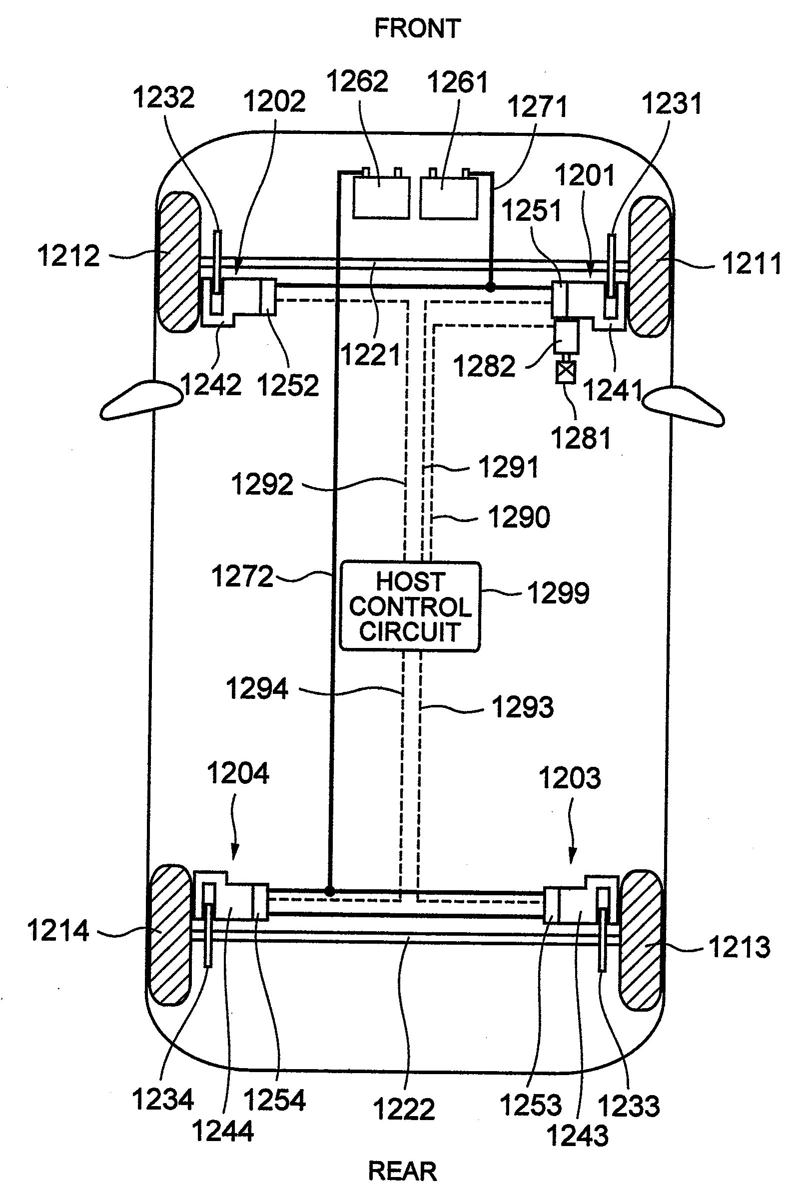
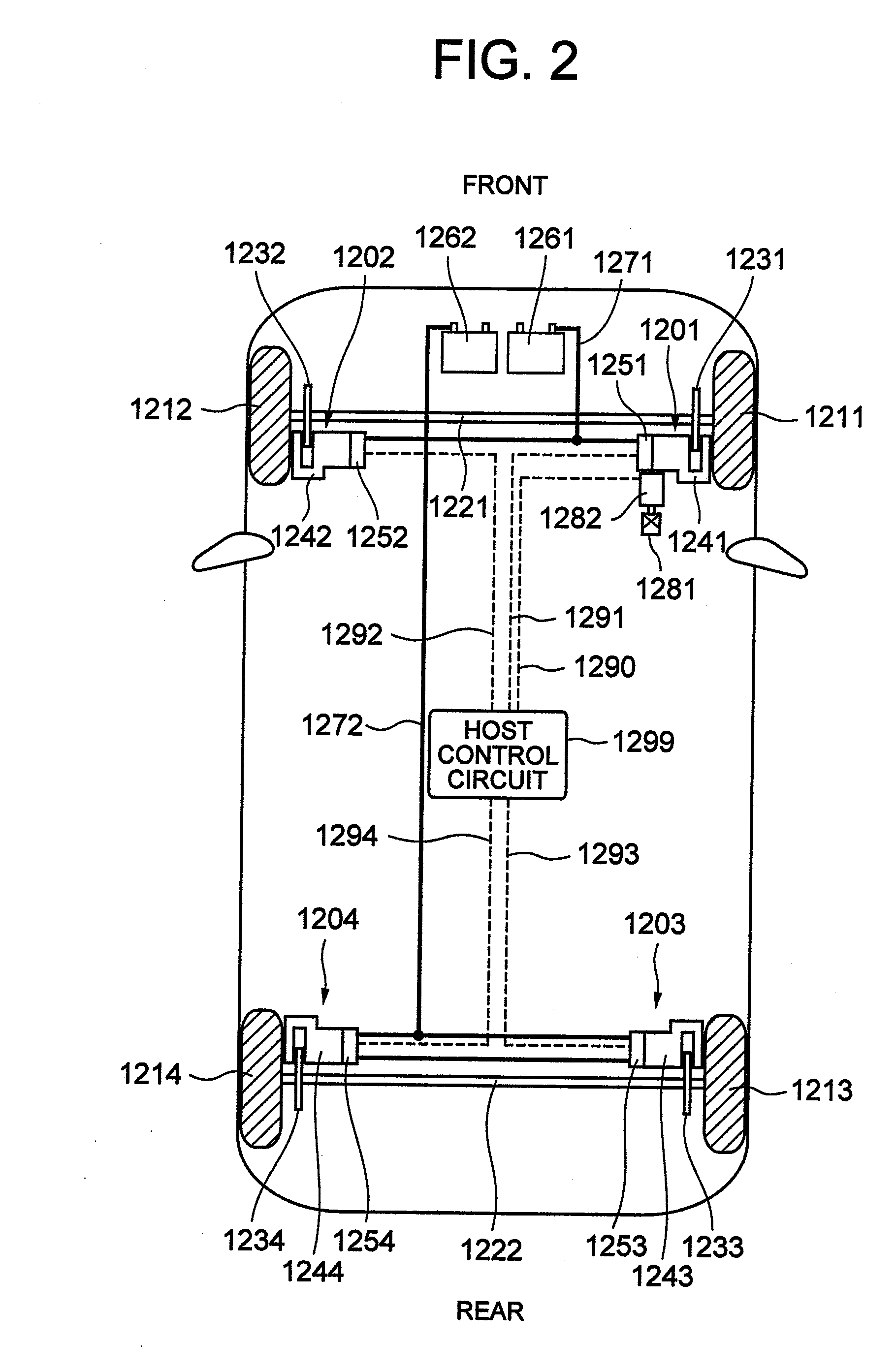
[0024]FIG. 2 is a schematic diagram of a braking system of a vehicle mounting an electric braking apparatus. Description of a drive mechanism for traveling is omitted here.

[0025]A first electric braking device 1201 is mounted at a location near a right front wheel 1211 and an axel 1221. A second electric braking device 1202 is mounted at a location near a left front wheel 1212 and the axel 1221. A third electric braking device 1203 is mounted at a location near a right rear wheel 1213 and an axel 1222. A fourth electric braking device 1204 is mounted at a location near a left rear wheel 1214 and the axel 1222.

[0026]While the basic structure of the electric braking devices 1201 to 1204 is the same, it is preferable that the first and second electric braking devices 1201 and 1202 in association with the front wheels generate a larger braking force than the third and fourth electric braking devices 1203 and 1204 in association with the rear wheels.

[0027]Disk rotors 1231 and 1232 are fi...


PUM


Abstract

An electric braking apparatus including a motor for pressing brake pads on disks, a metal housing for housing the motor, a positive-polarity power line for transmitting power from a battery to the electric motor, a negative-polarity ground line for connecting the electric motor to the ground of a vehicle, and a conductor for electrically connecting the metal housing to the negative polarity of battery or the negative-polarity of an inverter.

Description

BACKGROUND OF THE INVENTION[0001]The present invention relates to an electric braking apparatus applicable to an automobile and the like.[0002]Recently, in a brake applicable to an automobile or the like, a contrivance for not only assisting mere driver's braking operation but also, with the aim of improving safety, generating a braking force necessary to avoid collision irrespective of the driver's braking operation and automatically stabilizing the vehicle behavior has been considered in various ways.[0003]It has hitherto been known that in order to automatically generate the braking force as above or to materialize delicate requests made by the driver, an electric motor is controlled in accordance with a traveling status and an environmental status by using an electric braking apparatus having, for example, the electric motor, a reduction gear for reducing the rotation of the electric motor, a rotation / linear motion conversion mechanism for converting the rotation decelerated by ...

Claims


Application Information

Patent Timeline
Patent Type & Authority Applications(United States)
IPC IPC(8): B60T13/00
CPCB60T13/741F16D65/18F16D2066/001F16D2066/005F16D2121/24F16D2125/38F16D2125/40H02K5/225H02K11/0073H02K2211/03H02K11/33
Inventor KIKUCHI, KENJIKURAMOCHI, YUICHIMABUCHI, YUICHI
Owner HITACHI LTD
Why Eureka
Try Eureka