Voice Coil Module

a voice coil and module technology, applied in the field of voice coil modules, can solve the problems of high cost and difficulty in manufacturing, significant power loss, and the demerit of conventional vcm in that power loss is more significant, so as to prevent distortion of an optical axis, accurate control, and avoid power loss

Active Publication Date: 2008-12-11
SK HYNIX INC
View PDF3 Cites 35 Cited by
  • Summary
  • Abstract
  • Description
  • Claims
  • Application Information

AI Technical Summary

Benefits of technology

[0012]In order to solve the aforementioned problems, an object of the present invention is to provide a voice coil module (VCM) in which power loss can be avoided in a state that a lens is fixed to a specific position, an unclear image can be avoided by preventing vibration of the lens when a minute vibration occurs while an image is captured or by preventing distortion of an optical axis, accurate control can be achieved by measuring a present displacement according to operations of the VCM, and an erroneous operation can be avoided.

Problems solved by technology

Manufacturing of a small stepping motor requires a high cost and a difficult technique.
In the VCM having this structure, a current having a constant magnitude and direction has to be continuously provided so that the lens 110 can maintain a constant position, resulting in a significant amount of power loss.
That is, although the VCM can be manufactured in a small size due to its cost competitiveness, simply operation, and simple structure, the conventional VCM has a demerit in that power loss is more significant than the ultrasonic motor since, in order to fix the lens 110 to a specific position, a constant current has to be continuously supplied to a driving coil.
Such power loss is a major stumbling block when it comes to put the VCM to the market for a small-sized product using a battery.
Furthermore, the conventional VCM is not provided with a method for determining whether the VCM is correctly controlled and for measuring a present position of the VCM.
Therefore, a problem lies in that it is difficult to accurately control the VCM, and an erroneous operation cannot be prevented.

Method used


Image

  • Voice Coil Module
  • Voice Coil Module
  • Voice Coil Module

Examples


Embodiment Construction

[0021]Hereinafter, exemplary embodiments of the present invention will be described in detail with reference to the accompanying drawings.

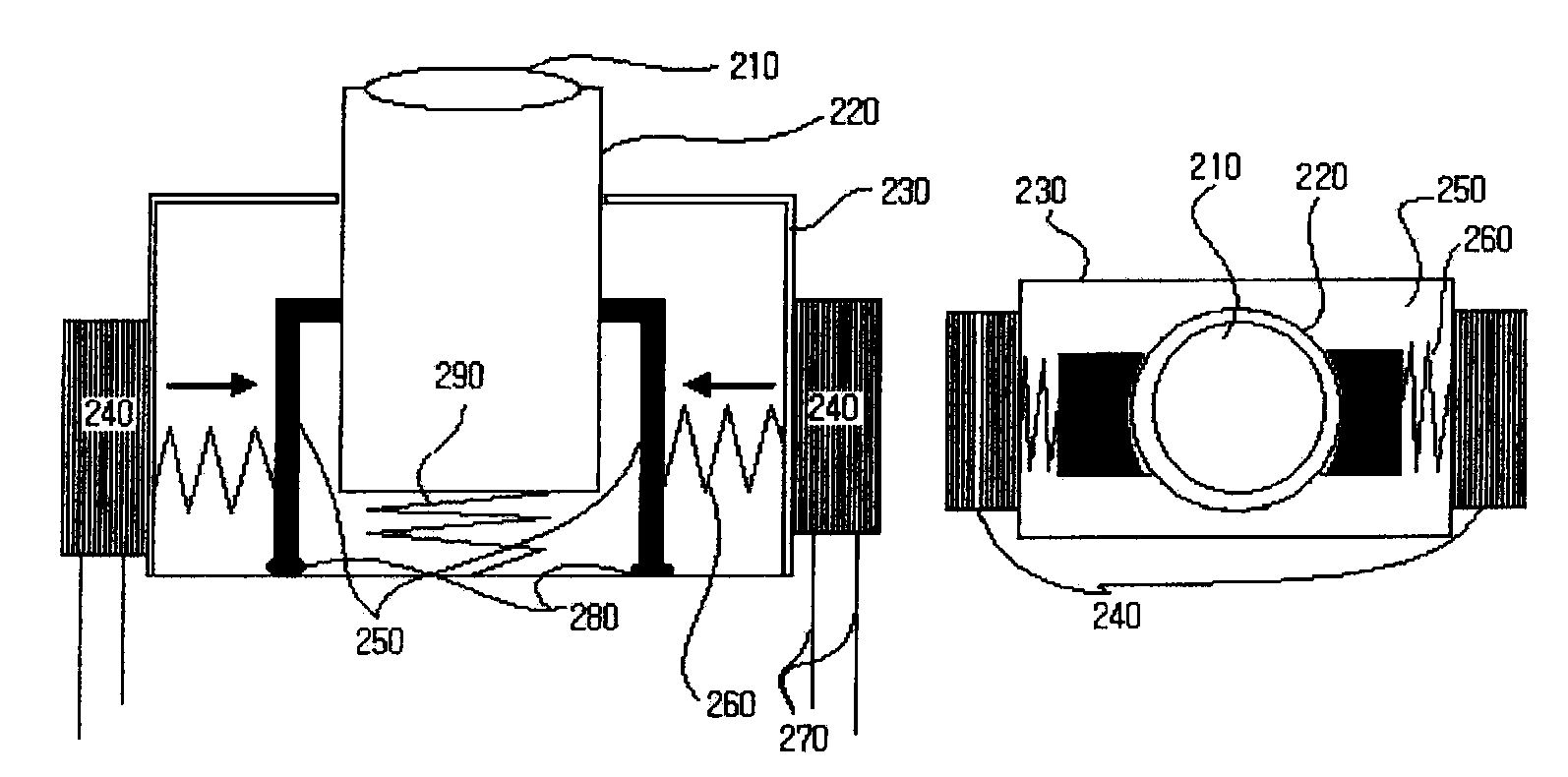
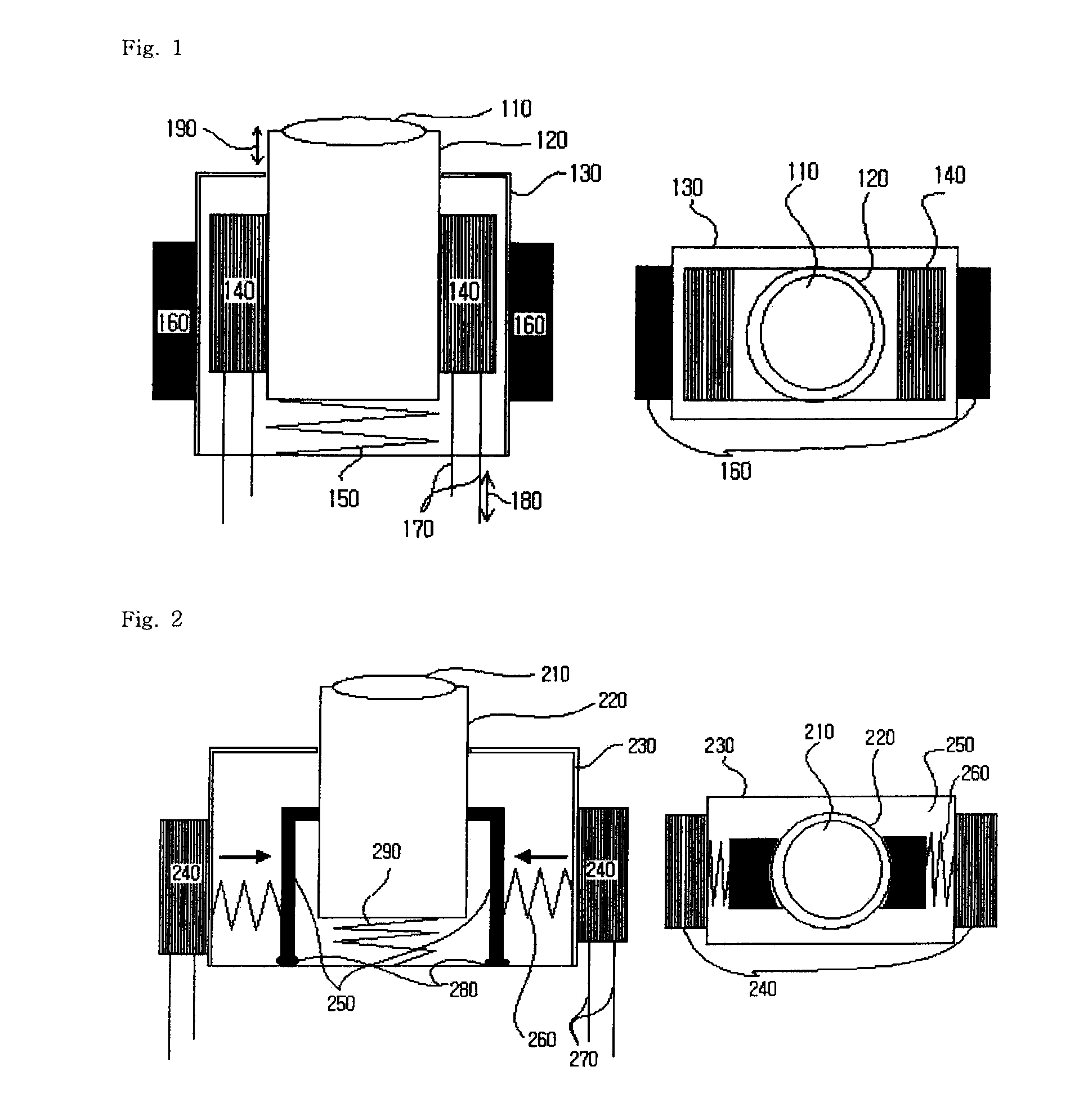
[0022]FIG. 2 illustrates a lens fixing unit of a VCM according to an embodiment of the present invention. The lens fixing unit includes a lens 210, an lens barrel 220, a casing 230, an lens barrel fixing pin 250, a coil 240 for driving the lens barrel fixing pin 250, a first spring 290 for supporting the lens barrel 220, and a second spring 260.

[0023]The lens barrel 220, which is vertically movable along with the lens 210, is held by the lens barrel fixing pin 250 by a strength of the second spring 260 fixed to the casing 230. The lens barrel fixing pin 250 is a ferromagnetic body or a paramagnetic body. A direct connection 280 is made between the lens barrel fixing pin 250 and the casing 230. Further, the lens barrel fixing pin 250 is connected with the casing 230 and the second spring 260 so that the lens barrel fixing pin 250 can move only in a...


PUM


Abstract

The present invention relates to a voice coil module (VCM), and more particularly, to a VCM used for lens fixation and displacement measurement in order to prevent and control power consumption. Accordingly, in the VCM, power is not additionally consumed in order to maintain a specific position of the lens in a state that a focus of the lens is adjusted. Further, the lens is not moved and an optical axis is not distorted when a vibration occurs while an image is captured. Furthermore, the lens can be accurately controlled by measuring the present position of the lens.

Description

BACKGROUND OF THE INVENTION[0001]1. Field of the Invention[0002]The present invention relates to a voice coil module (VCM), and more particularly, to a VCM used for lens fixation and displacement measurement in order to prevent and control power consumption.[0003]2. Description of the Related Art[0004]A voice coil module (VCM) generally includes a permanent magnet and a coil. An attractive force or a repulsive force is produced between an induced magnetic field generated by a current flowing through the coil and a magnetic filed generated by the permanent magnet. Displacement of a lens occurs due to a spring force as well as the attractive force or the repulsive force.[0005]The VCM advantageously has a simple structure and a low manufacturing cost. Therefore, the VCM is widely used in a driving unit of an automatic focusing device provided to a small image sensor. The driving unit of the automatic focusing device may be implemented with a stepping motor or an ultrasonic motor.[0006]...

Claims


Application Information

Patent Timeline
Patent Type & Authority Applications(United States)
IPC IPC(8): G02B27/64
CPCG02B7/08H02K7/1085H02K33/18H02K41/0356B60Q1/08B60Q1/0023B60Q2300/112B60Q2200/38B60Y2400/303
Inventor LEE, BYOUNG SU
Owner SK HYNIX INC
Why Eureka
Try Eureka