Power controller

a technology of power controller and structure, which is applied in the direction of motor/generator/converter stopper, dynamo-electric converter control, instruments, etc., can solve the problems of increasing shortening the life of the switching element or the motor, and similar problems, so as to prevent the deterioration of the total power loss of the system and reduce the temperature of the electronic components.

Inactive Publication Date: 2015-04-23
TOYOTA JIDOSHA KK
View PDF4 Cites 32 Cited by
  • Summary
  • Abstract
  • Description
  • Claims
  • Application Information

AI Technical Summary

Benefits of technology

[0018]An advantage provided according to the present invention is to prevent deterioration of the total power loss of a system while reducing a rise in

Problems solved by technology

In this condition, overvoltage or overcurrent caused by the oscillation of the voltage may shorten the life of the switching elements or the motor.
However, under the adjusted condition of the output voltage of the boost converter to a voltage minimizing the total power loss of the system in

Method used


Image

  • Power controller
  • Power controller
  • Power controller

Examples


Embodiment Construction

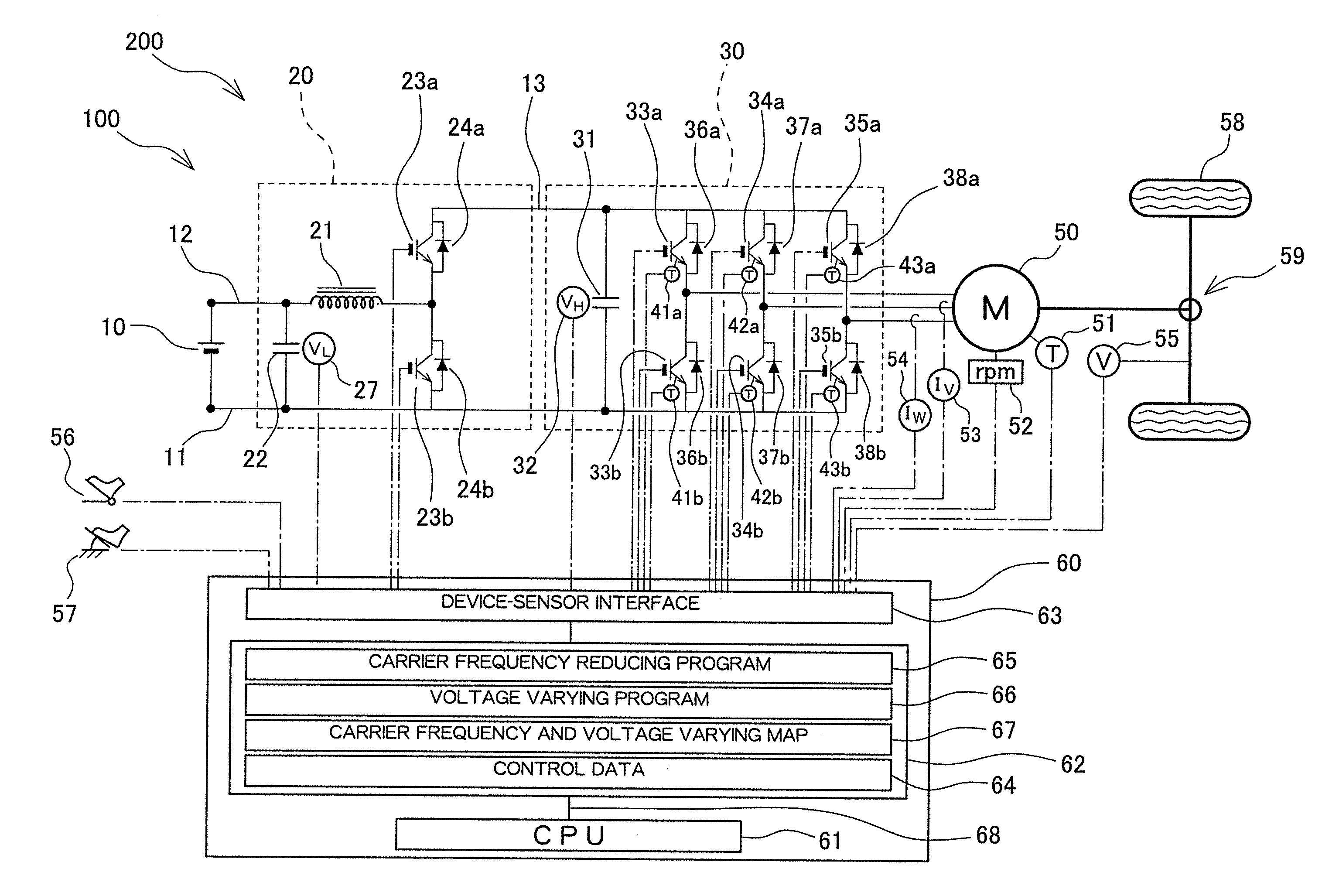
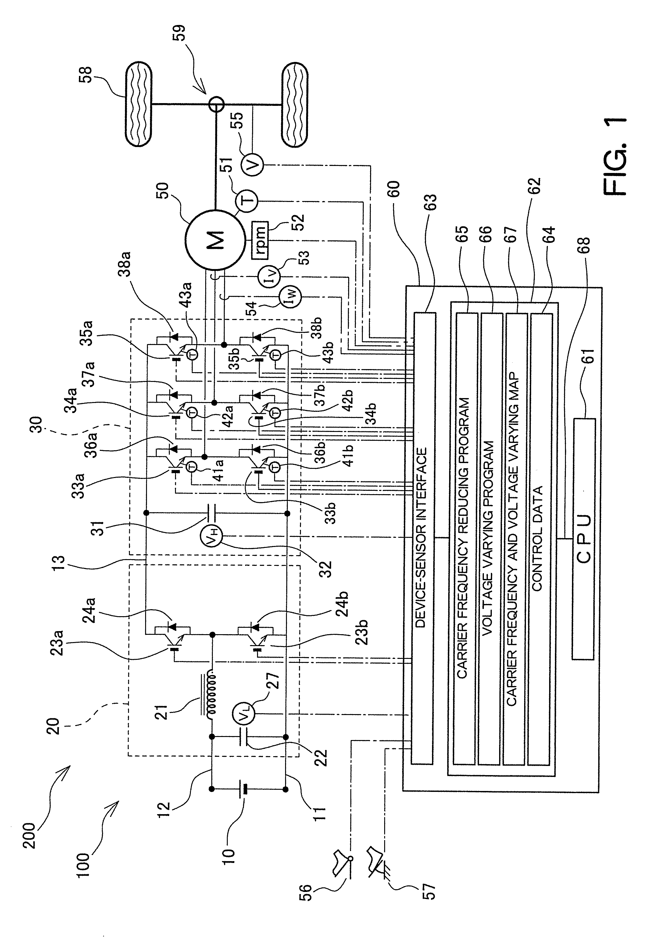
[0028]An embodiment according to the present invention is hereinafter described with reference to the drawings. As illustrated in FIG. 1, a power controller 100 according to the present invention includes: a battery 10; a boost converter 20 which boosts voltage of DC power supplied from the battery 10 and outputs voltage-boosted DC power; an inverter 30 which converts the voltage-boosted DC power received from the boost converter 20 into AC power by turning a plurality of switching elements 33a through 35a and 33b through 35b on and off at a carrier frequency fmg, and supplies the AC power to a motor 50 for vehicle driving; and a control unit 60 which controls the output voltage of the boost converter 20 and the carrier frequency fmg of the inverter 30.

[0029]The boost converter 20 and the inverter 30 include a grand circuit 11 connected with the negative side of the battery 10 and common to both the boost converter 20 and the inverter 30, a low-voltage circuit 12 connected with the ...


PUM


Abstract

A power controller includes a boost converter, an inverter, and a control unit controlling the output voltage of the boost converter and the carrier frequency of the inverter. The control unit includes a carrier frequency reducing program which reduces the carrier frequency to an LC resonance upper limit frequency while maintaining a set value of the output voltage of the boost converter at a system loss minimization voltage at the time of reduction of the carrier frequency from the set frequency, and a voltage varying program which changes the carrier frequency to a first varied frequency calculated based on a first predetermined temperature or lower and the temperatures of the respective switching elements, and changes the set value of the output voltage of the boost converter to a voltage at which the LC resonance upper limit frequency becomes the first varied frequency.

Description

PRIORITY INFORMATION[0001]This application claims priority to Japanese Patent Application No. 2013-216200, filed on Oct. 17, 2013, which is incorporated herein by reference in its entirety.TECHNICAL FIELD[0002]The present invention relates to a structure of a power controller which boosts battery voltage and supplies the boosted voltage to a motor, and to an operation method of this controller.BACKGROUND ART[0003]An electric motor vehicle, such as an electric automobile driven by a motor, and a hybrid automobile driven by outputs of a motor and an engine, includes a power controller which boosts voltage of a power source battery using a boost converter, converts DC power after voltage boost by the boost converter into AC power using an inverter, and supplies the AC power to a vehicle driving motor.[0004]The inverter included in the power controller converts DC power into AC power such as three-phase AC power by turning a plurality of switching elements on and off at a carrier freque...

Claims


Application Information

Patent Timeline
IPC IPC(8): H02P6/08H02M3/155H02M7/48
CPCH02P6/085H02M7/53871H02P27/06H02P27/085B60L15/007B60L2240/421B60L2240/425B60L2240/526B60L2240/529B60L2240/527Y02T10/64H02M1/0048H02M1/327H02M1/007
Inventor NOBE, DAIGOSATO, RYOJIHAYASHI, KAZUHITO
Owner TOYOTA JIDOSHA KK
Why Eureka
Try Eureka