Remote control system and method of television control

Active Publication Date: 2011-11-03
CLOUD NETWORK TECH SINGAPORE PTE LTD
View PDF3 Cites 2 Cited by
  • Summary
  • Abstract
  • Description
  • Claims
  • Application Information

AI Technical Summary

Problems solved by technology

However, it is inconvenient for the user to operate remote controls with ever increasing function buttons to operate the TV set.

Method used


Image

  • Remote control system and method of television control
  • Remote control system and method of television control
  • Remote control system and method of television control

Examples


Embodiment Construction

[0010]The disclosure is illustrated by way of example and not by way of limitation in the figures of the accompanying drawings in which like references indicate similar elements. It should be noted that references to “an” or “one” embodiment in this disclosure are not necessarily to the same embodiment, and such references mean at least one.

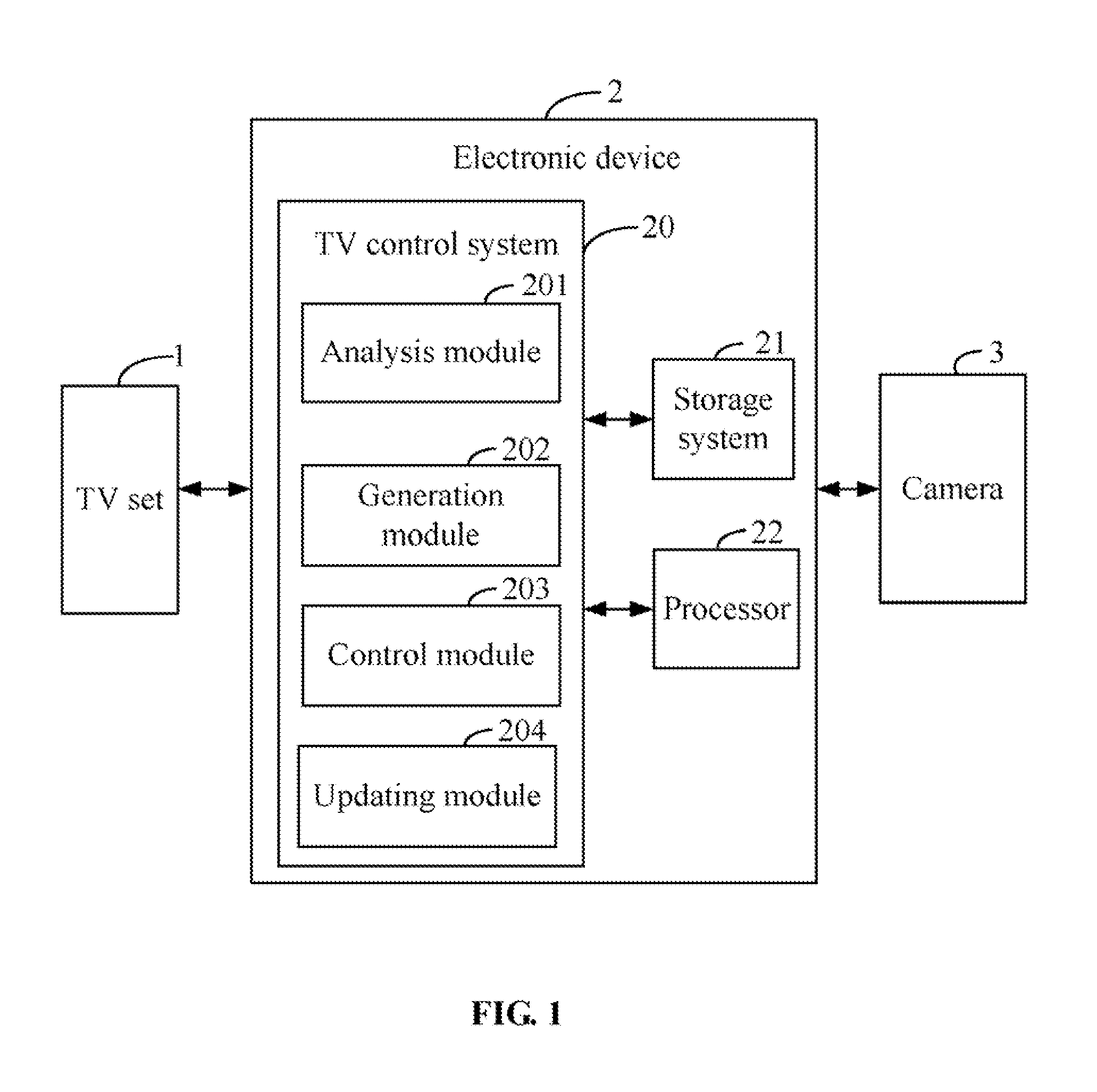
[0011]FIG. 1 is a schematic diagram of one embodiment of an electronic device 2 connected with a television (TV) set 1 and a camera 3. In the embodiment, the electronic device 2 can be used to remotely control the TV set 1 to perform various functions, such as switching from one TV channel to another TV channel, for example. The electronic device 2 includes a TV control system 20, a storage system 21, and a processor 22. It should be apparent that FIG. 1 shows only one example of an architecture for electronic device 2 and may include more or fewer components than shown, or a different configuration of the various components in other embodiments....


PUM


Abstract

A remote control method controls a television (TV) set to perform functions using an electronic device. The method controls a camera connected with the electronic device to capture an image in front of the TV set when the TV set is turned on. The method analyzes the captured image to determine whether a hand image of a user exists in the captured image, and extracts the hand image from the captured image upon the condition that the hand image exists in the captured image to determine a hand sign of the user according to the extracted hand image. The method generates a remote control signal for controlling the TV set according to the determined hand sign, and controls the TV set to perform a function according to the remote control signal.

Description

BACKGROUND[0001]1. Technical Field[0002]Embodiments of the present disclosure relate generally to remote control systems and methods, and more particularly to a system and method for remotely controlling a television.[0003]2. Description of Related Art[0004]Television (TV) sets that are controlled by a remote control are well known in the art. For example, a user can control a TV set to switch from one channel to another channel by pressing buttons of the remote control. A typical remote control includes a frame to support a plurality of mechanical function buttons that execute predetermined functions. The more functions the remote control has, the more buttons are disposed on the remote control. Therefore, the frame should be designed as large as possible to hold the function buttons. However, it is inconvenient for the user to operate remote controls with ever increasing function buttons to operate the TV set.BRIEF DESCRIPTION OF THE DRAWINGS[0005]FIG. 1 is a schematic diagram of ...

Claims


Application Information

Patent Timeline
IPC IPC(8): H04N5/44
CPCH04N21/42204H04N21/44218H04N21/4223
Inventor LEE, HOU-HSIENLEE, CHANG-JUNGLO, CHIH-PING
Owner CLOUD NETWORK TECH SINGAPORE PTE LTD
Why Eureka
Try Eureka