
Fiber optic housings configured to accommodate fiber optic modules/cassettes and fiber optic panels, and related components and methods.

a fiber optic and housing technology, applied in the field of fiber optic hardware, can solve the problems of affecting the installation and/or reconfiguration of the equipment, affecting the operation of the equipment, and the availability of space in the equipment rack for supporting additional fiber optic equipment may only be present in the existing installed housing

Active Publication Date: 2011-11-03
CORNING OPTICAL COMM LLC
View PDF2 Cites 172 Cited by
  • Summary
  • Abstract
  • Description
  • Claims
  • Application Information

AI Technical Summary

Benefits of technology

[0018]In another embodiment, a fiber optic housing comprising a stackable shelf, a panel clip, a front stacker assembly, and a rear stacker assembly is provided. The panel clip, the front stacker assembly, and the rear stacker assembly removably attach to the stackable shelf to allow the stackable shelf to accommodate one or both of a fiber optic module and a fiber optic panel interchangably. The

Problems solved by technology

However in these examples, the correct housing type to support the specific additional fiber optic equipment needed may not be readily available thus delaying installations and / or reconfigurations.
Even if the correct housing types are readily available, they come at additional cost and requirements for inventory space to store the different types of housings needed to support the different types of fiber optic equipment that may be added or reconfigured.
Further, the available space in an equipment rack for supporting additional fiber optic equipment may only be present in existing installed housings that are not fully populated.
However, the housings with available space may not be configured to support the particular type of fiber optic equipment to be added.

Method used


Image

  • Fiber optic housings configured to accommodate fiber optic modules/cassettes and fiber optic panels, and related components and methods.
  • Fiber optic housings configured to accommodate fiber optic modules/cassettes and fiber optic panels, and related components and methods.
  • Fiber optic housings configured to accommodate fiber optic modules/cassettes and fiber optic panels, and related components and methods.

Examples


Embodiment Construction

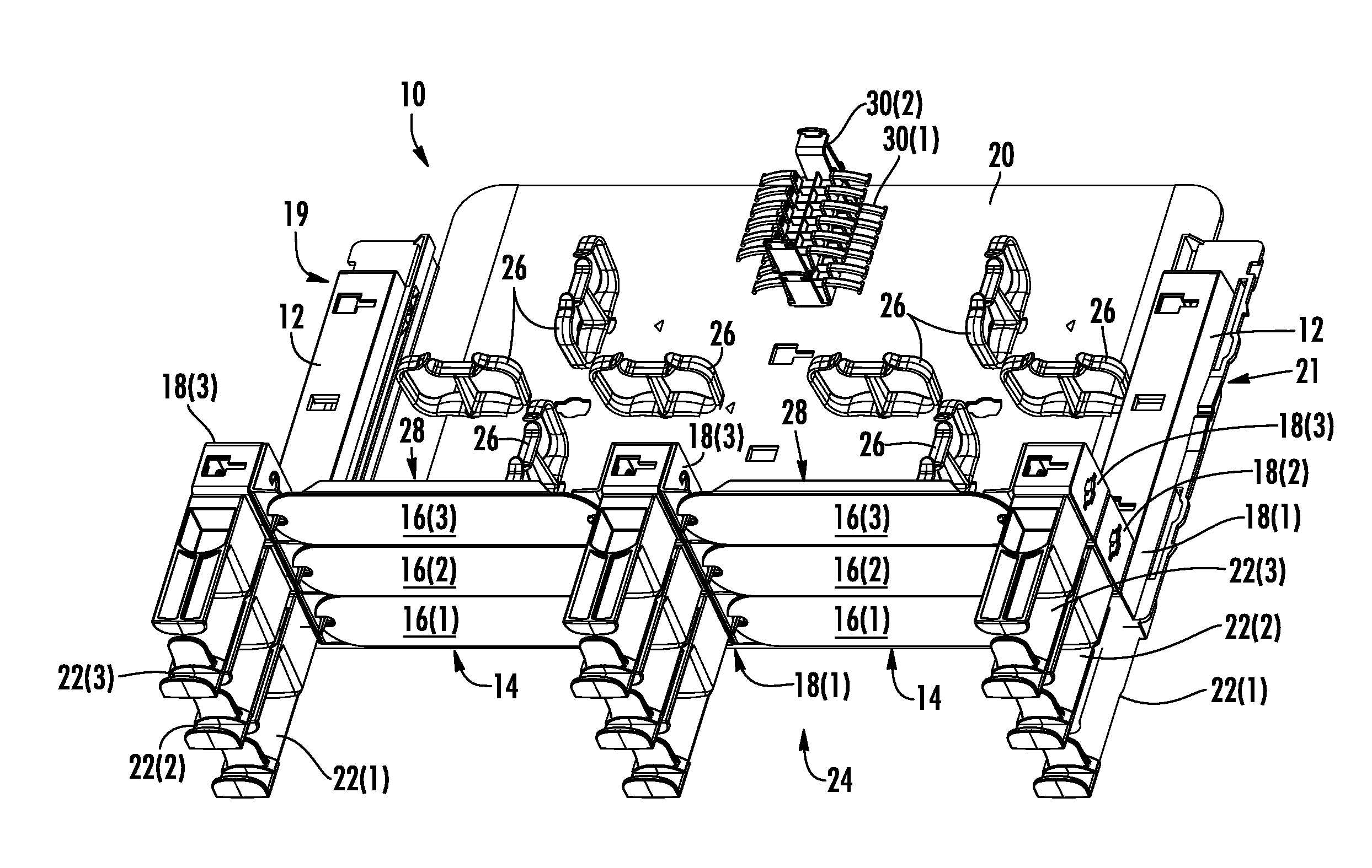
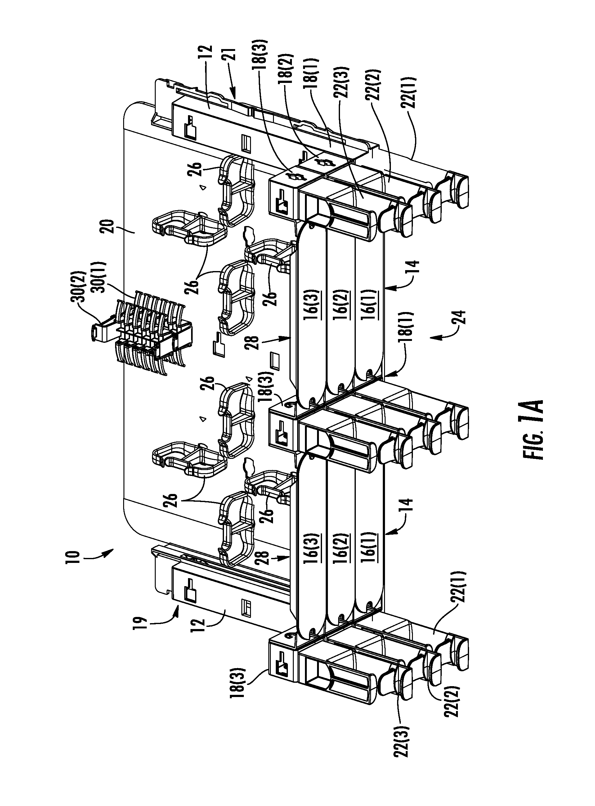
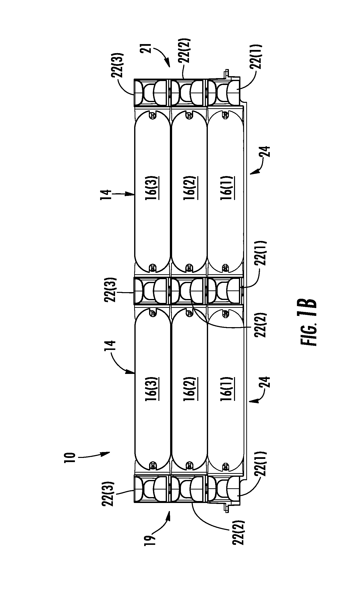
[0017]Embodiments disclosed in the detailed description include fiber optic housings configured to accommodate fiber optic modules / cassettes and fiber optic panels, and related components and methods. In one embodiment, a fiber optic apparatus is provided. The fiber optic apparatus is comprised of a fiber optic housing. The fiber optic apparatus is also comprised of one or more removable panel clips disposed in the fiber optic housing. Each of the one or more removable panel clips includes at least one receptacle configured to receive an insert of a fiber optic panel to support the fiber optic panel in the fiber optic housing.

[0018]In another embodiment, a fiber optic housing comprising a stackable shelf, a panel clip, a front stacker assembly, and a rear stacker assembly is provided. The panel clip, the front stacker assembly, and the rear stacker assembly removably attach to the stackable shelf to allow the stackable shelf to accommodate one or both of a fiber optic module and a f...


PUM


Abstract

Fiber optic housings configured to accommodate fiber optic modules / cassettes and fiber optic panels are disclosed. In one embodiment, a fiber optic apparatus is provided and comprised of a fiber optic housing and one or more removable panel clips. Each of the one or more removable panel clips includes at least one receptacle configured to receive an insert of a fiber optic panel to support the fiber optic panel in the fiber optic housing. In another embodiment, a fiber optic shelf configured to be supported in a fiber optic housing is provided. The fiber optic shelf comprises a mounting surface and one or more removable panel clips attached to the mounting surface that each includes at least one receptacle configured to receive an insert of a fiber optic panel to support the fiber optic panel in the mounting surface. Related components and methods are also disclosed.

Description

RELATED APPLICATIONS[0001]The present application claims priority to U.S. Provisional Patent Application Ser. No. 61 / 329,925, filed Apr. 30, 2010, entitled “Fiber Optic Housing Adapted to Accommodate Both Modules and Panels,” the disclosure of which is relied upon and incorporated herein by reference in its entirety.[0002]The present application is related to U.S. Provisional Patent Application Ser. No. 61 / 329,948, filed Apr. 30, 2010, entitled “Stackable Shelf For A Fiber Optic Housing,” the disclosure of which is relied upon and incorporated herein by reference in its entirety.[0003]The present application is also related to U.S. patent application Ser. No. ______, filed ______, 2010, entitled “Stackable Shelves For A Fiber Optic Housing, and Related Components and Methods,” the disclosure of which is relied upon and incorporated herein by reference in its entirety.[0004]The present application is also related to U.S. Provisional Patent Application Ser. No. 61 / 329,898, filed Apr. ...

Claims


Application Information

Patent Timeline
IPC IPC(8): G02B6/46
CPCG02B6/4452G02B6/44526G02B6/4455
Inventor COTE, MONIQUE L.FRAZIER, BRENT M.GIRAUD, WILLIAM J.JAY, RAYMOND G.RODRIGUEZ, DIANA
Owner CORNING OPTICAL COMM LLC
Learn More