Sectorization in Distributed Antenna Systems, and Related Components and Methods

a distributed antenna and antenna technology, applied in the field of distributed antenna systems, can solve the problems of limiting the capacity increasing the cost of the distributed antenna system, and reducing the capacity of each supported radio band in a given antenna coverage area

Active Publication Date: 2011-11-03
CORNING OPTICAL COMM LLC
View PDF13 Cites 138 Cited by
  • Summary
  • Abstract
  • Description
  • Claims
  • Application Information

AI Technical Summary

Problems solved by technology

However, providing remote antenna units that support multiple radio bands can also limit capacity in the distributed antenna system.
The bandwidth of the remote antenna unit is split among the multiple radio bands thus reducing the capacity of each supported radio band in a given antenna coverage area.
However, providing additional remote antenna units increases the cost of the distributed antenna system.
Providing additional remote antenna units to provide additional capacity may be delayed after initial installation and provided as needed, but higher installation costs may be associated with retrofitting an existing installation with additional remote antenna units.

Method used


Image

  • Sectorization in Distributed Antenna Systems, and Related Components and Methods
  • Sectorization in Distributed Antenna Systems, and Related Components and Methods
  • Sectorization in Distributed Antenna Systems, and Related Components and Methods

Examples


Embodiment Construction

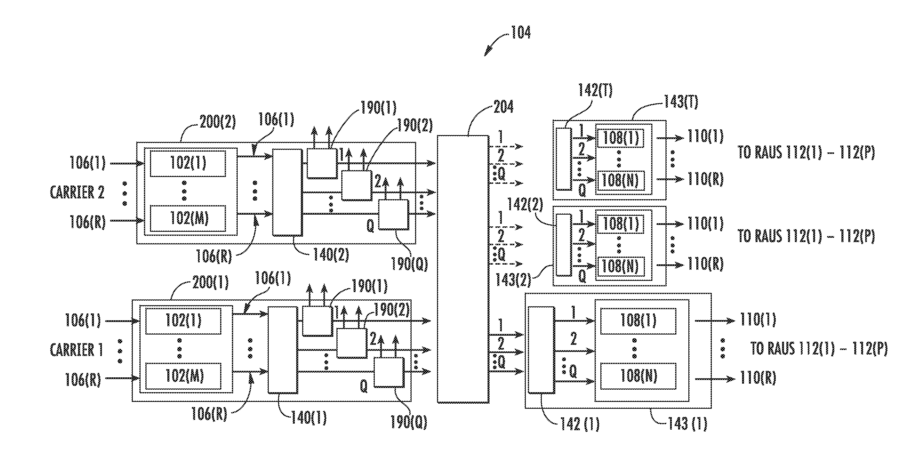
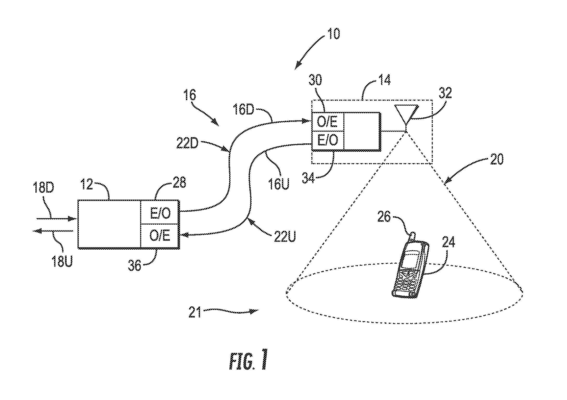
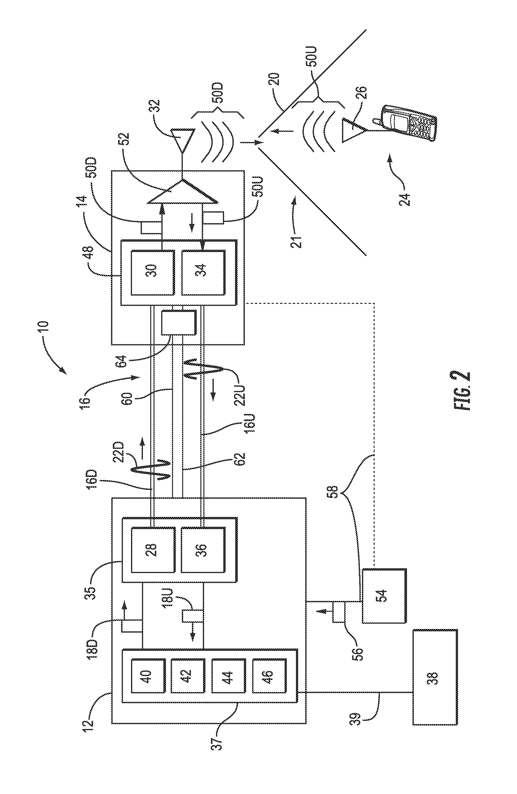
[0011]Embodiments disclosed in the detailed description include providing sectorization in distributed antenna systems, and related components and methods. As one non-limiting example, the distributed antenna systems may be optical fiber-based distributed antenna systems. The antenna units in the distributed antenna systems can be sectorized. In this regard, one or more radio bands distributed by the distributed antenna systems can be allocated to one or more sectors. The antenna units in the distributed antenna systems are also allocated to one or more sectors. In this manner, only radio frequency (RF) communications signals in the radio band(s) allocated to given sector(s) are distributed to the antenna unit allocated to the same sector(s). The bandwidth capacity of the antenna unit is split among the radio band(s) allocated to sector(s) allocated to the antenna unit. The sectorization of the radio band(s) and the antenna units can be configured and / or altered based on capacity ne...


PUM


Abstract

Embodiments disclosed provide sectorization in distributed antenna systems, and related components and methods. The antenna units in the distributed antenna systems can be sectorized. In this regard, one or more radio bands distributed by the distributed antenna systems can be allocated to one or more sectors. The antenna units in the distributed antenna systems are also allocated to one or more sectors. In this manner, only radio frequency (RF) communications signals in the radio band(s) allocated to given sector(s) are distributed the antenna unit allocated to the same sector(s). The bandwidth capacity of the antenna unit is split among the radio band(s) allocated to sector(s) allocated to the antenna unit. The sectorization of the radio band(s) and the antenna units can be configured and / or altered based on capacity needs for given radio bands in antenna coverage areas provide by the antenna units.

Description

RELATED APPLICATIONS[0001]The present application is related to U.S. Provisional Patent Application Ser. No. 61 / 330,383 filed on May 2, 2010 and entitled “Optical Fiber-Based Distributed Communications Systems, and Related Components and Methods,” which is incorporated herein by reference in its entirety.[0002]The present application is also related to U.S. Provisional Patent Application Ser. No. 61 / 230,463 filed on Jul. 31, 2009 and entitled “Optical Fiber-Based Distributed Antenna Systems, Components, and Related Methods for Calibration Thereof,” which is incorporated herein by reference in its entirety.[0003]The present application is also related to U.S. Provisional Patent Application Ser. No. 61 / 230,472 filed on Jul. 31, 2009 and entitled “Optical Fiber-Based Distributed Antenna Systems, Components, and Related Methods for Monitoring the Status Thereof,” which is incorporated herein by reference in its entirety.BACKGROUND[0004]1. Field of the Disclosure[0005]The technology of t...

Claims


Application Information

Patent Timeline
Patent Type & Authority Applications(United States)
IPC IPC(8): H04B10/10
CPCH04B10/25753H04B10/25752H04W88/085
Inventor BERLIN, IGORCUNE, WILLIAM P.GREENE, JASON E.SAUER, MICHAELSCHMIDT, GERALD B.
Owner CORNING OPTICAL COMM LLC
Why Eureka
Try Eureka