Distributed antenna system for wireless network systems

a wireless network and distributed antenna technology, applied in the field of wireless transceiver systems, can solve the problems of high cost for each service provider to extend coverage to increase capacity by deploying their own micro/pico cells and/or distributed antennas, and facilities may not permit the installation of such equipment by multiple service providers, so as to improve signal quality, increase capacity and coverage area, the effect of reducing the cos

Active Publication Date: 2013-01-01
COMMSCOPE TECH LLC
View PDF59 Cites 150 Cited by
  • Summary
  • Abstract
  • Description
  • Claims
  • Application Information

AI Technical Summary

Benefits of technology

[0006]Embodiments of the present invention provide a distributed antenna system (“DAS”) that can be used by multiple wireless service providers to increase the capacity and the coverage area of multiple communication systems without the need for each provider to incur the cost of deploying one or more micro / pico cells or DAS. To that end, embodiments of the invention are capable of simultaneously distributing signals between collocated base stations, operated by multiple service providers, and remote or fixed subscriber units. The signals may encompass multiple RF bands, multiple channels within those bands, and multiple air interface standards. Embodiments of the invention may provide to wireless service providers a solution that, when compared to micro cells or pico cells, allows them to cover certain environments at a lower cost with similar or even improved signal quality.

Problems solved by technology

Further, these techniques may also be used to extend coverage to areas within the cell site where RF propagation may be limited by obstruction, such as in buildings and tunnels, or to areas where the amount of traffic (revenue) does not justify the investment required for a complete base station 24.
The cost for each service provider to extend coverage to increase capacity by deploying their own micro / pico cells and / or distributed antennas may be quite high.
Further in some areas where RF propagation is poor, such as sporting venues or shopping malls, the owners of such facilities may not permit the installation of such equipment by multiple service providers for aesthetic reasons or because of space limitations.

Method used


Image

  • Distributed antenna system for wireless network systems
  • Distributed antenna system for wireless network systems
  • Distributed antenna system for wireless network systems

Examples


Embodiment Construction

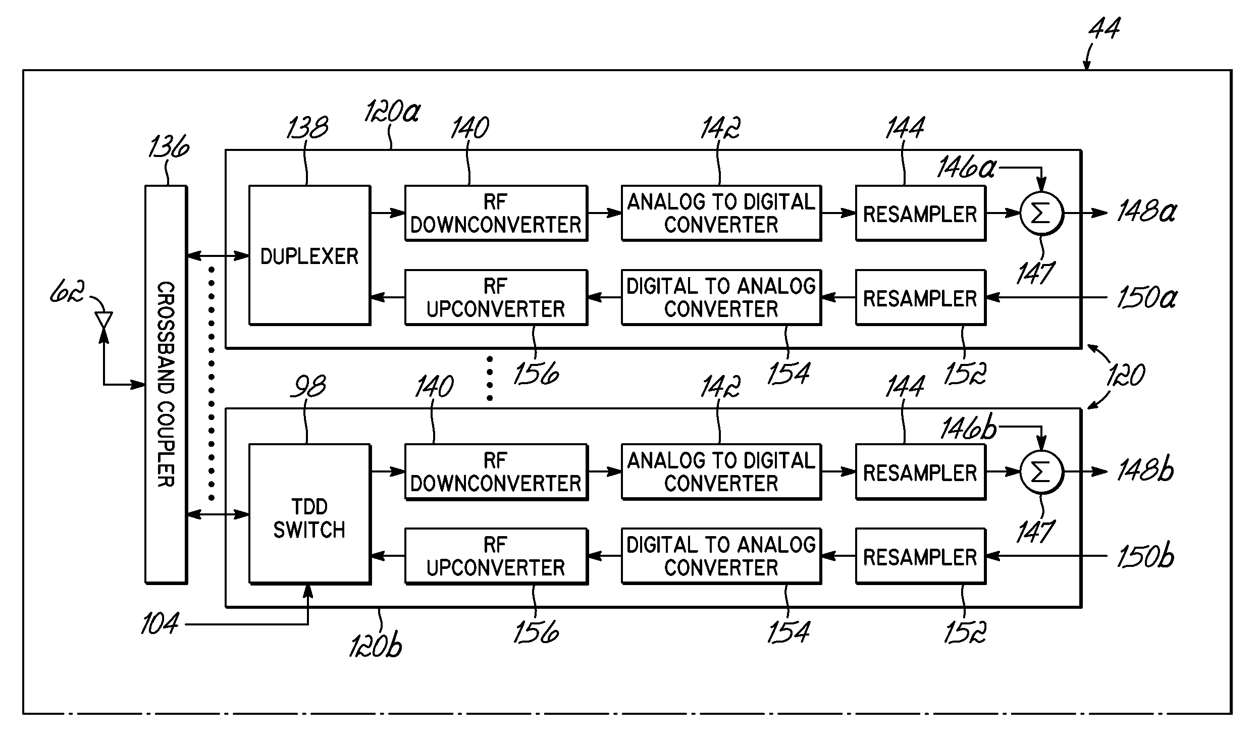
[0028]Embodiments of the present invention provide a distributed antenna system (“DAS”) that can be used by multiple service providers to increase the capacity and the coverage area of multiple communication systems without the need for each provider to incur the cost of deploying one or more micro / pico cells or DAS. To do this, embodiments of the present invention are capable of simultaneously distributing signals between collocated base stations operated by multiple service providers, employing multiple RF bands, multiple channels within those bands, and multiple air interface standards and mobile or fixed subscriber units.

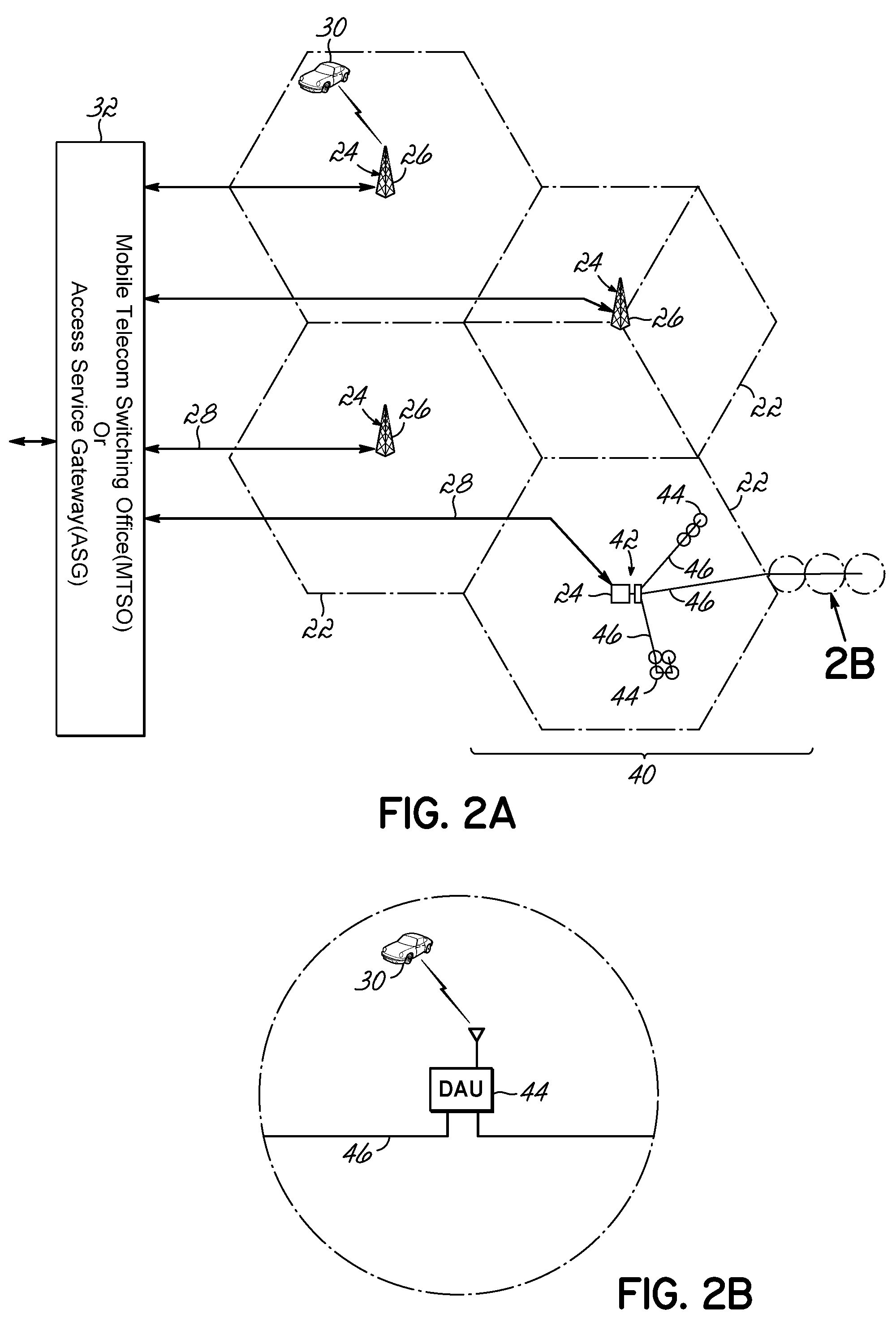
[0029]The system architecture of the invention is such that the number of RF bands / air interfaces, the number of service providers that can be accommodated, and the number of distributed antennas can be tailored for each coverage scenario to minimize cost. One possible implementation 40 of the system may be seen in the exemplary embodiment illustrated in FIGS. 2...


PUM


Abstract

A distributed antenna system is provided for communicating with a plurality of base stations. The distributed antenna system includes a system controller and a master unit communicating with at least one of the plurality of base stations. A remote unit communicates over a high data rate media with the master unit and / or a downstream remote unit. Alternatively, the distributed antenna system includes a controller and a digital time / space crosspoint switch controlled by the controller. A digitizing transceiver is in communication with the digital time / space crosspoint switch. The crosspoint switch is configured to transmit and receive digital data through the digitizing transceiver.

Description

FIELD OF THE INVENTION[0001]The present invention is directed to wireless transceiver systems for use in wireless communication systems, and specifically is directed to a distributed antenna system for the wireless transceiver system.BACKGROUND OF THE INVENTION[0002]Contemporary cellular phone systems and broadband wireless metropolitan networks 20, as shown in FIG. 1, are generally divided into a number of cells 22 distributed in a pattern to preclude co-channel interferences and provide coverage of mobile and fixed subscriber units operating within the service area of the system. Each cell 22 includes a base station 24 that employs radio frequency (RF) transceiver equipment, antennas 26, and wire line 28 communication equipment. Mobile / fixed subscriber units 30 within the geographic area of the cell site use RF transceiver equipment to communicate with RF transceivers within the base station 24. The base station 24 relays voice and data traffic to / from the subscriber mobile units ...

Claims


Application Information

Patent Timeline
Patent Type & Authority Patents(United States)
IPC IPC(8): H04B7/02H04J14/02H04L27/00
CPCH04W88/085H04W88/06H04W16/14H04B10/25753H04B10/2575
Inventor KUMMETZ, THOMASMCALLISTER, DONALDPAGANO, CARMINEYAN, HONGJUCLEARY, DENNIS M.HANSON, VANSCHMALISCH, MATHIASEISENWINTER, STEFAN
Owner COMMSCOPE TECH LLC
Why Eureka
Try Eureka