

Row running control system and vehicle
a control system and row technology, applied in the field of row running control system, can solve the problems of difficult to disturb the behavior of the row, propagation of errors in inter-vehicle distance to the rear vehicles,
- Summary
- Abstract
- Description
- Claims
- Application Information
AI Technical Summary
Benefits of technology
Problems solved by technology
Method used
Image

Examples
first embodiment
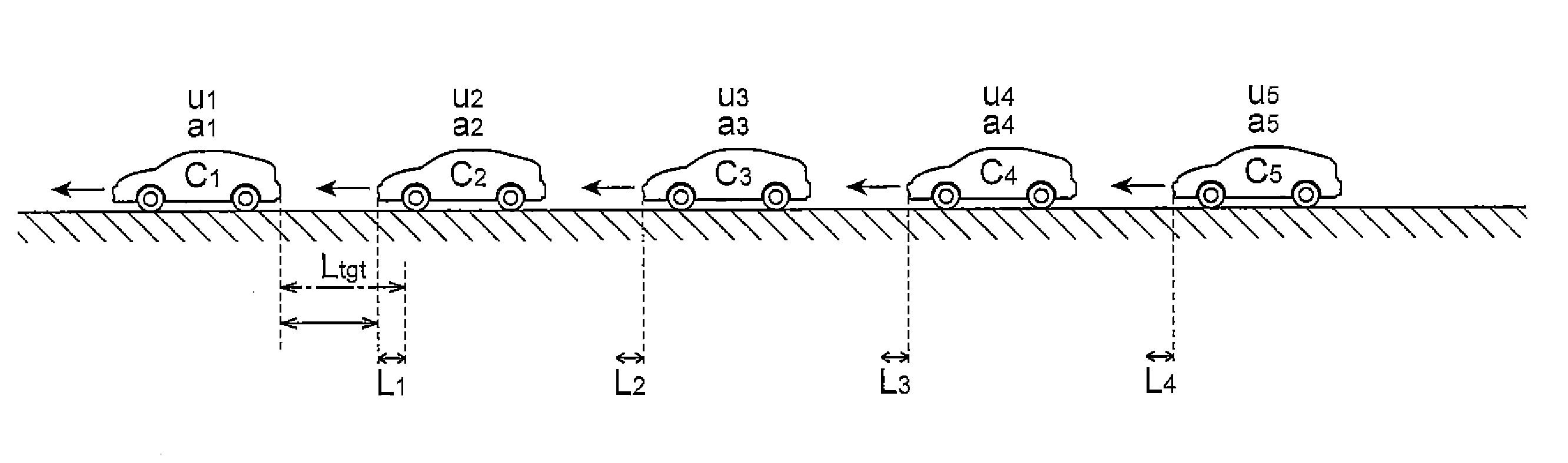
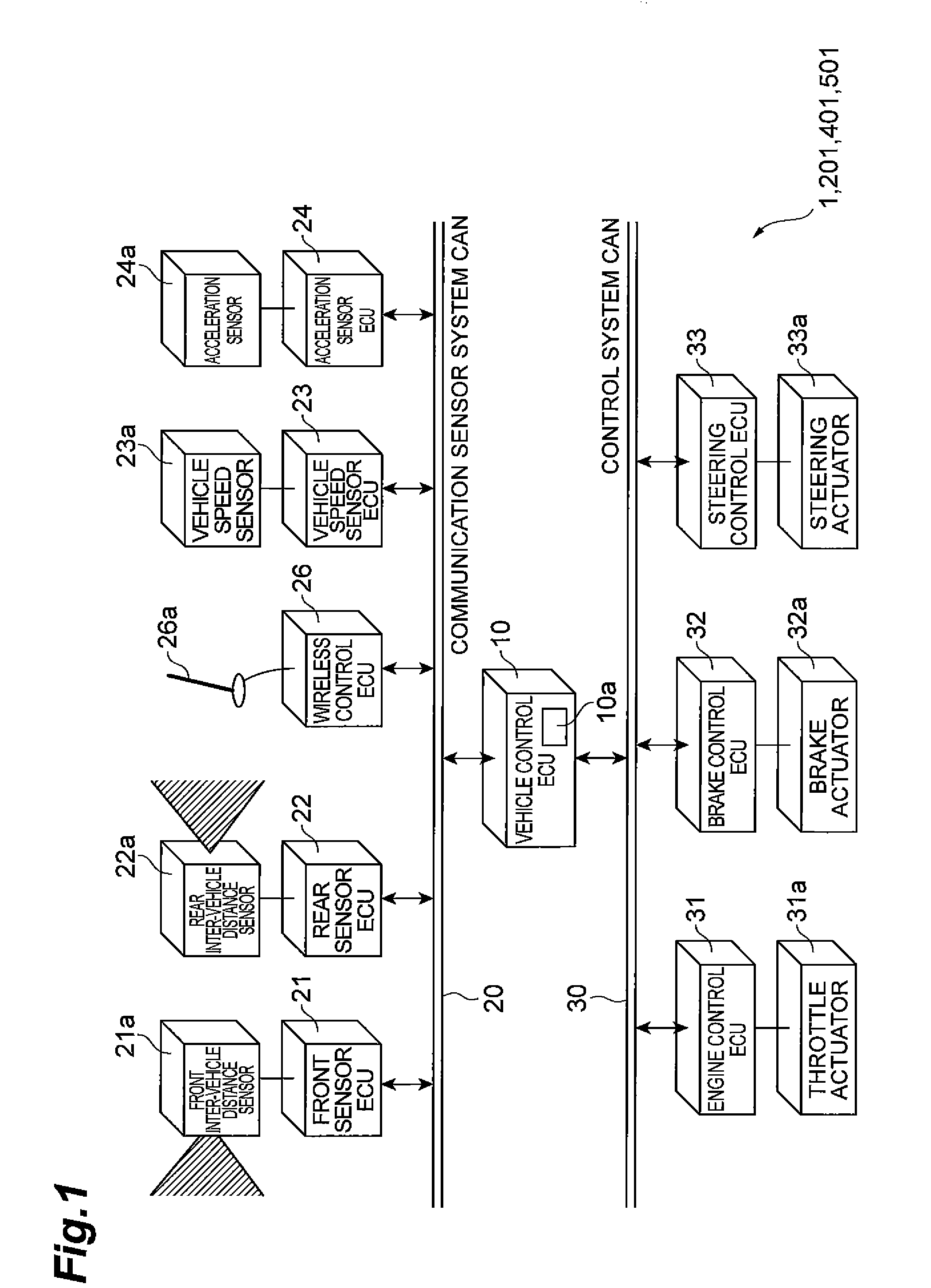
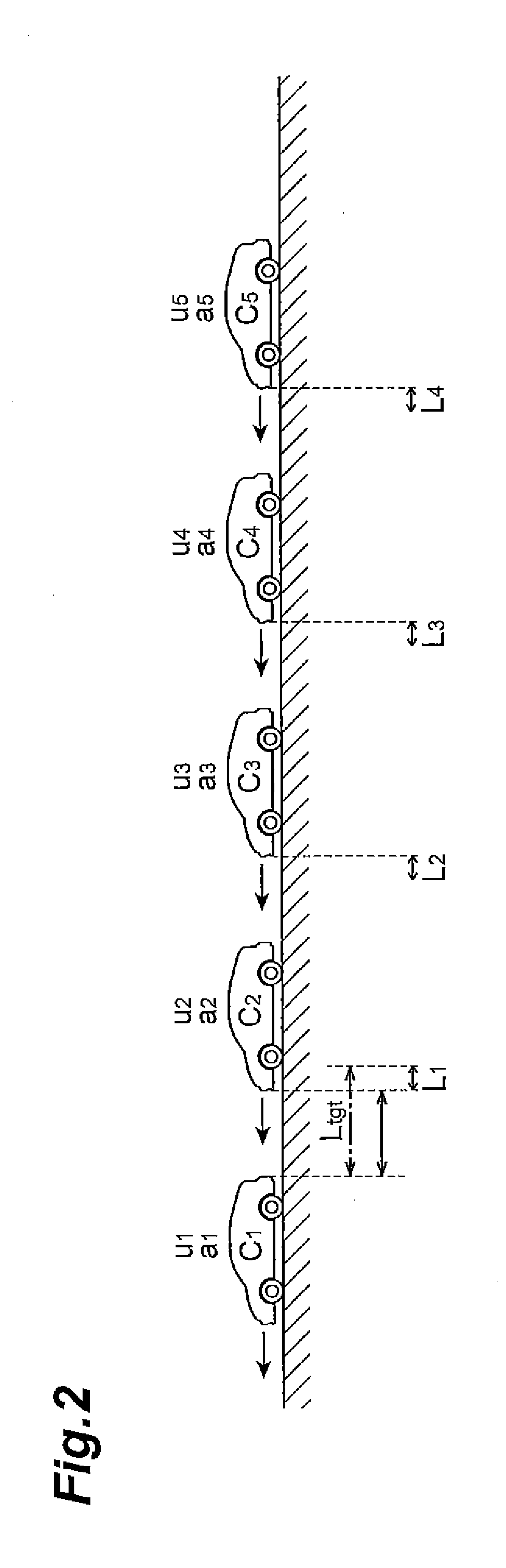
[0042]A row running control system 1 shown in FIG. 1 is a system that controls the respective running states of a plurality of vehicles so that the plurality of vehicles can run in a row. By means of the row running control system 1, a row running is realized in which a plurality of vehicles run while being arranged longitudinally in a row at relatively narrow inter-vehicle distances. In the row running control system 1, although row running constituted by any arbitrary number of vehicles can be realized, herein, as shown in FIG. 2, a case will be described as an example where the row running is performed by five vehicles C1, C2, C3, C4 and C5.
[0043]In addition, in the following description, as shown in FIG. 2, the acceleration of nth (n=1, 2, . . . , 5) vehicle Cn counted from the lead of the row is represented by “an”, the velocity of the vehicle Cn is represented by “Vn”, and an acceleration instruction value of the vehicle Cn is represented by “un”. Furthermore, an inter-vehicle...
second embodiment
[0100]Next, a second embodiment of a row running control system according to the present invention will be described. The physical configuration of a row running control system 201 of the present embodiment is the same as that of the row running control system 1 as shown in FIG. 1, and thus repeated description will be omitted.
[0101]According to the aforementioned row running control system 1, even when the disturbance is added to the lead vehicle C1, since the movement alone of the succeeding vehicles C2 to C5 is used to compensate for the disturbance, in this case, an excessive load may be applied to the succeeding vehicles C2 to C5.
[0102]Thus, the row running control system 201 is different from the row running control system 1 in which the running states of only the succeeding vehicles C2 to C5 are controlled in that the running states of all of the five constituent vehicles C1 to C5 are controlled. That is, in the row running control system 201, the control intervenes in the ru...
third embodiment
[0119]Next, a third embodiment of a row running control system according to the present invention will be described. As shown in FIG. 13, a row running control system 301 of the present embodiment further includes an operation switch 29a, in addition to the row running control system 1. The operation switch 29a is connected to the vehicle control ECU 10 via the communication sensor system CAN 20. The operation switch 29a receives the selection operation by a driver and transmits the operation to the vehicle control ECU 10 as an electric signal.
[0120]In the row running control system 301, the operation switch 29a (see FIG. 13), for example in the lead vehicle C1, can selectively switch between whether the running states of four succeeding vehicles C2 to C5 are controlled (called “a first type of control”), as in the row running control system 1, or the running states of all the vehicles C1 to C5 are controlled (called “a second type of control”), as in the row running control system ...
PUM
 Abstract
Description
Claims
Application Information