
Adjustment of imaging property in view-dependent rendering

Inactive Publication Date: 2011-11-10
CANON KK
View PDF9 Cites 80 Cited by
  • Summary
  • Abstract
  • Description
  • Claims
  • Application Information

AI Technical Summary

Benefits of technology

[0012]According to another aspect of the invention, an apparatus for displaying an image includes a display for displaying the image, and at least one processor coupled via a bus to a memory. The processor is programmed to control one or more of a relative position and orientation determining unit for determining a relative position and orientation of the display in relation to a viewer's head, an image rendering unit fo

Problems solved by technology

However, it has been a challenge to provide an intuitive and user-friendly rendering of the multi-dimensional data generated by such techniques on a conventional display.
That is, while computational photographic techniques and / or the integration of multiple views of a scene can provide image data with multiple layers of information, it can be difficult for the user to access and view this information in a way that is both intuitive and meaningful to the user.
However, while such view-dependent rendering techniques have been used to facilitate viewing of computer-generated virtual models, they generally have not been deemed suitable for the rendering of images captured from real scenes.
This is at least in part due to the fact that changing the perspective of real images while viewing with a view-dependent rendering technique can cause a loss in the proper focus of the image.
Also, the amount of image data captured by computational photography systems and other multidimensional techniques can make view-dependent rendering of the image data associated with a real scene both prohibitively expensive and time consuming.
Furthermore, techniques such as the image-refocusing method described by Ng are generally not suitable for use with view-dependent rendering systems, because the requirement that the user select the area of interest via gesturing does not allow for the fast refocus response time needed for seamless viewing of an image with view-dependent rendering.

Method used


Image

  • Adjustment of imaging property in view-dependent rendering
  • Adjustment of imaging property in view-dependent rendering
  • Adjustment of imaging property in view-dependent rendering

Examples


Embodiment Construction

[0023]Embodiments of the present invention provide for the adjustment of an imaging property in a view dependent rendering of an image, thereby enhancing the quality and experience of viewing of the image. Aspects of the invention may be applicable, for example, to the viewing of image data obtained by computational photography methods, such as image data corresponding to captured light field images.

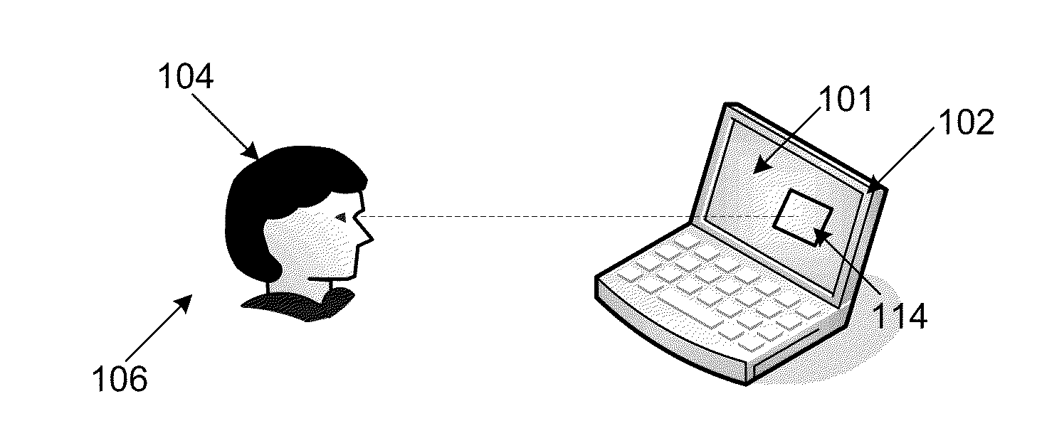
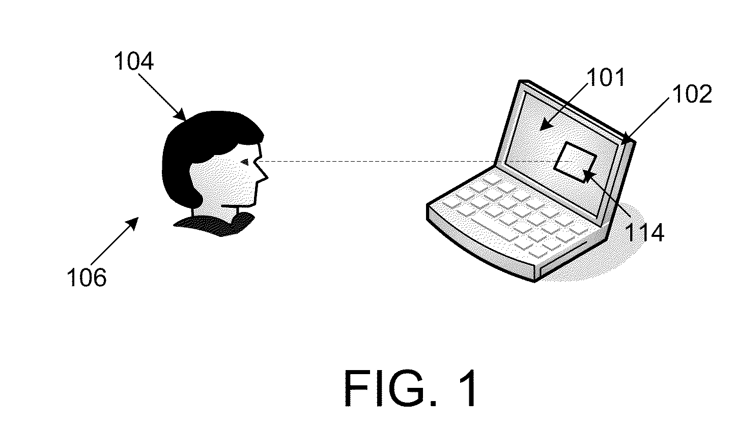
[0024]Pursuant to these embodiments, an apparatus 100 comprising a display 102 may be provided for displaying the view dependent rendering of the image thereon, as shown for example in FIG. 1. The display 102 may comprise, for example, one or more of an LCD, plasma, OLED and CRT, and / or other type of display 102 that is capable of rendering an image thereon based on image data. In the embodiment as shown in FIG. 1, the apparatus 100 comprises an information processing apparatus that corresponds to a laptop computer having a display 102 incorporated therein, however, aspects of the invent...


PUM


Abstract

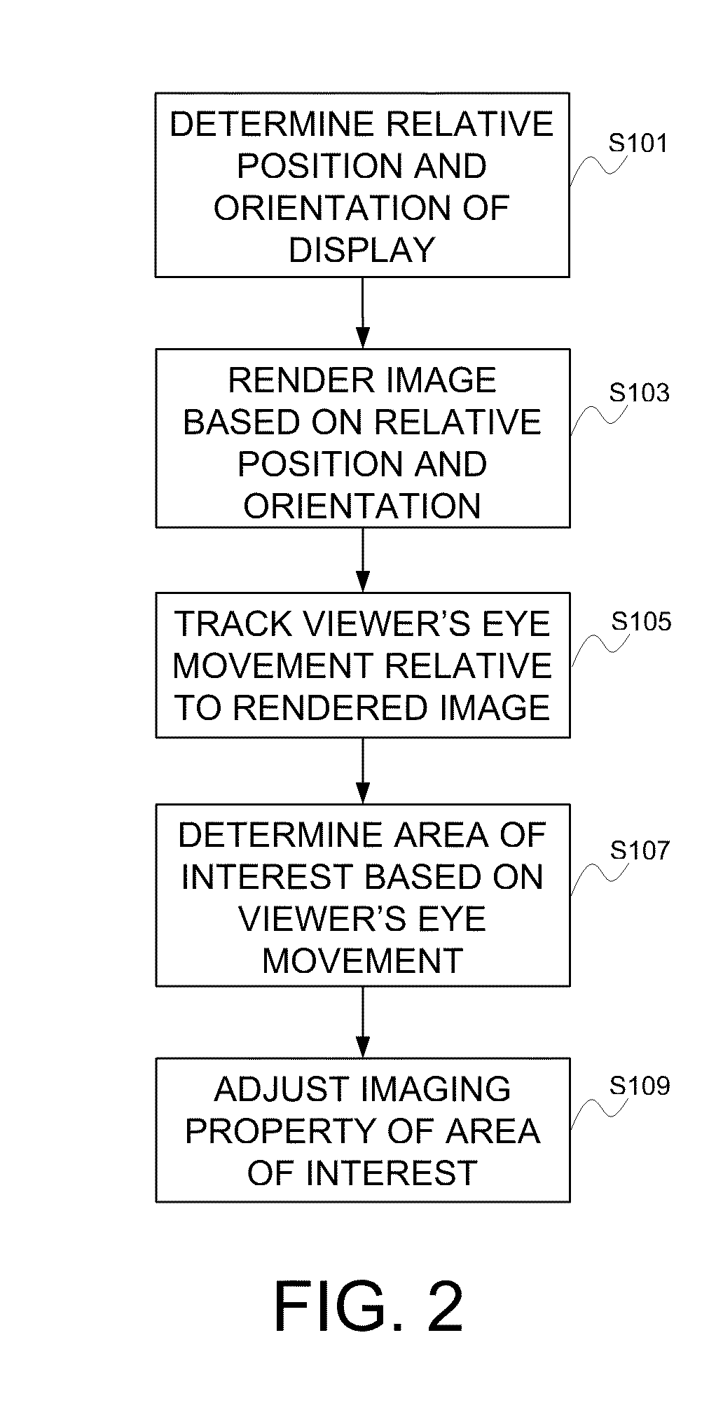
An image is displayed by determining a relative position and orientation of a display in relation to a viewer's head, and rendering an image based on the relative position and orientation. The viewer's eye movement relative to the rendered image is tracked, with at least one area of interest in the image to the viewer being determined based on the viewer's eye movement, and an imaging property of the at least one area of interest is adjusted.

Description

BACKGROUND OF THE INVENTION[0001]1. Field of the Invention[0002]Aspects of the present invention relate to an apparatus and method for the adjustment of an imaging property in a view-dependent rendering of an image. In particular, aspects of the present invention may relate to the adjustment and / or control of imaging properties such as at least one of the focus, sharpness, white balance, dynamic range, resolution, brightness and tone mapping in an image rendered in a view-dependent manner, for example in the focusing of a view-dependent rendering of an extended depth of field image.[0003]2. Description of the Related Art[0004]Computational photography is an increasing area of interest in the field of digital photography. Computational photography generally encompasses photographic and / or computational techniques that extend beyond the limitations of traditional photography, to provide images and / or image data that typically could not be otherwise obtained with conventional technique...

Claims


Application Information

Patent Timeline
IPC IPC(8): G06F3/033
CPCG06F3/04845G06T2215/16G06T15/50G06T15/20
Inventor IMAI, FRANCISCOHAIKIN, JOHN S.
Owner CANON KK
Learn More