Linear Lighting System

a lighting system and linear technology, applied in the field of lighting equipment, can solve the problems of frequent (at least annually) lamp failure, uneven lighting of the traffic surface and tunnel walls,

Inactive Publication Date: 2011-11-10
LSI INDS
View PDF9 Cites 33 Cited by
  • Summary
  • Abstract
  • Description
  • Claims
  • Application Information

AI Technical Summary

Benefits of technology

[0016]The housing also may have a gasket to create a moisture seal between the longitudinal side of the light-transmitting window and the pocket or receiving portion of the arm of the housing. The housing also comprises structure for enclosing, preferably sealing off, the opposed longitudinal ends of the elongated housing. The light sources can have an associated light-controlling reflector having a proximal opening disposed around the base of the light sources, and a distal opening defined by a distal rim disposed adjacent to the inner surface of the elongated window to create a light barrier that prevents light from escaping between the rim and the inner surface of the window.

Problems solved by technology

Tunnel and bridge lighting have used incandescent, fluorescent and more recently high intensity discharge (HID) lamps that can provide adequate amounts of lighting, but which have several drawbacks, including frequent (at least annually) lamp failures and uneven lighting of the traffic surface and tunnel walls.
The variability in the types of tunnels and driving conditions makes it a challenge to develop a lighting system that can be installed and easily adapted to any tunnel.

Method used


Image

  • Linear Lighting System
  • Linear Lighting System
  • Linear Lighting System

Examples


Embodiment Construction

Linear Luminaire

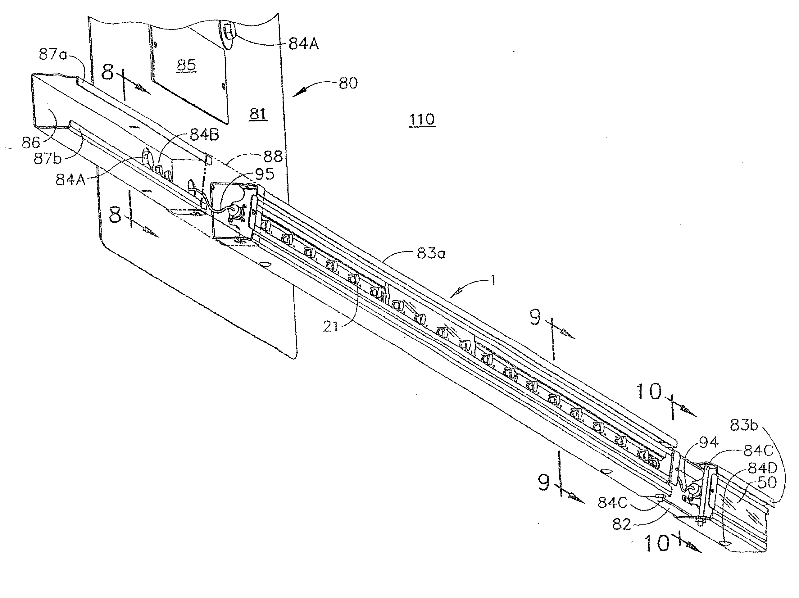
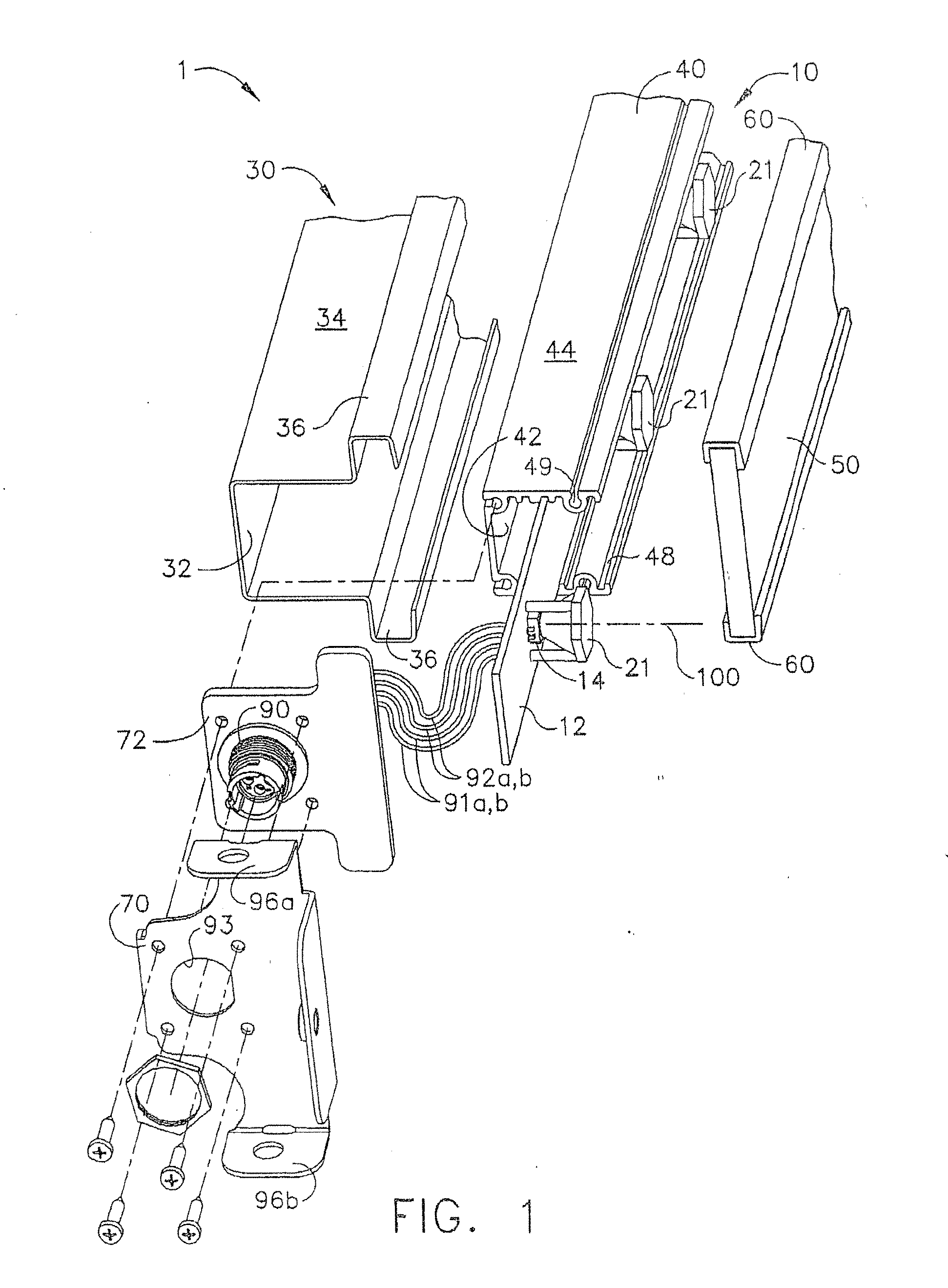
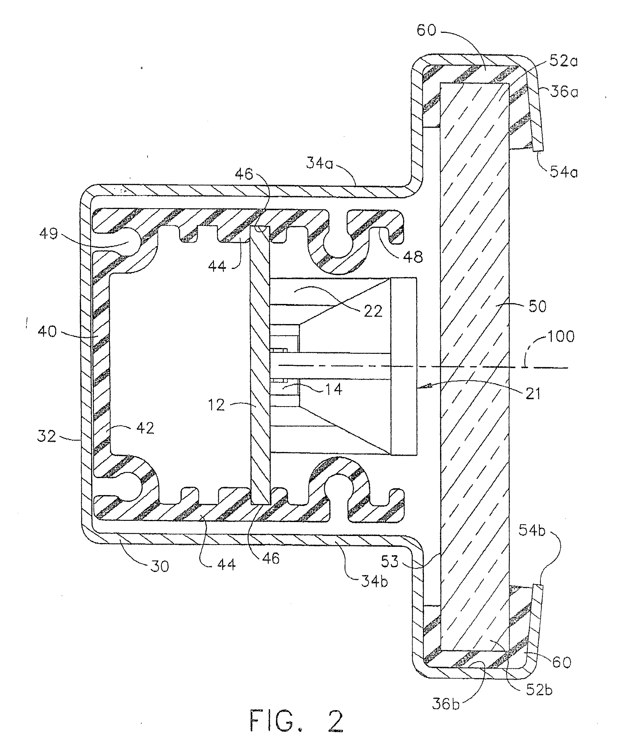
[0041]FIG. 1 shows an exploded view of a linear luminaire 1 consisting of a linear array light fixture 10, a housing 30, and a light-transmitting window 50. FIG. 2 shows a sectional view of the linear luminaire.

[0042]As shown in FIGS. 1 and 2, exemplary embodiments of a linear luminaire 1 can include a linear array light fixture 10 having an elongated light board 12 and a plurality of discrete light sources 14. Although the embodiments shown and described herein are shown and described as utilizing one or more LEDs as light sources, other light sources are also contemplated and may be substituted for the disclosed LED(s). In the embodiment depicted in FIGS. 1 and 2, LEDs are arranged in a substantially linear array along the length of the elongated light board 12. The array is shown as a single line of LEDs, centered at a longitudinal distance of at least 0.5 cm, and up to about 50 cm, though more typically at least 2 cm, and up to about 20 cm.

[0043]The linear array ...


PUM


Abstract

A luminaire for lighting a traffic surface in a tunnel is disclosed, wherein the luminaire has light sources disposed in an array for casting light on a traffic surface and structure for controlling and directing the light, such as a reflector or refractor lens. The luminaires are positioned along the length of the tunnel at angles to the traffic surface facilitating optimal use of the generated light. The luminaire is configured as a module that can be quickly installed into a support track mounted on the tunnel walls, and is dust and waterproof to endure mechanical and high pressure water cleaning by conventional tunnel washers. The luminaire is particularly well suited to employ light emitting diodes for generating and casting light.

Description

FIELD OF THE DISCLOSURE[0001]The present disclosure relates to a lighting apparatus and, more specifically, to a lighting apparatus for illuminating traffic tunnels. Embodiments of the present disclosure can be particularly useful for distributing light emitted from one or more light emitting diodes (LEDs), as described herein, but may be used with any type of light source.BACKGROUND OF THE DISCLOSURE[0002]LEDs have improved in terms of quality, performance and cost, and their use and popularity have been growing. LED lighting provides, and has the further potential, to reduce the power consumption per unit lumen. This application is a divisional application of U.S. patent application Ser. No. 12 / 064,844 filed Oct. 6, 2008, which is a 371 nationalization of PCT / US2006 / 034,718 filed Sep. 6, 2006, which claims priority to U.S. Provisional Patent Application No. 60 / 714,428 filed Sep. 6, 2005.[0003]Tunnel and bridge lighting have used incandescent, fluorescent and more recently high int...

Claims


Application Information

Patent Timeline
Patent Type & Authority Applications(United States)
IPC IPC(8): F21V7/00F21S4/00
CPCF21S2/005F21S4/008F21S8/033F21W2131/101F21Y2101/02F21V5/04F21S4/28F21Y2115/10
Inventor REED, MARK C.BOYER, JOHN DELMORE
Owner LSI INDS
Why Eureka
Try Eureka