Imager array interfaces

a technology of imager arrays and interfaces, applied in the field of imager arrays, can solve problems such as lack of ability

Active Publication Date: 2011-11-17
FOTONATION LTD
View PDF11 Cites 222 Cited by
  • Summary
  • Abstract
  • Description
  • Claims
  • Application Information

AI Technical Summary

Benefits of technology

[0022]A further embodiment of the invention also includes using control circuitry on the imager array to insert codes between the pixel data transmitted via the output interface, where the codes provide information identifying a focal plane.
[0023]Another embodiment of the invention also includes using control circuitry on the imager array to insert codes between the pixel data transmitted via the output interface, where the codes provide information identifying at least one row of pixels within a focal plane.
[0024]A still further embodiment of the invention also includes using control circuitry on the imager array to insert codes between the pixel data transmitted via the output interface, where the codes provide information identifying at least one of at least one column of pixels within a focal plane, the relative time of pixel data capture, the relative start time of the pixel data capture, the relative end time of the pixel data capture, the integration time of each focal plane, and the gain of each focal plane.
[0025]Still another embodiment of the invention also includes using control circuitry on the imager array to insert a line blanking interval between transmissions of buffered pixel data via the output interface.
[0026]A yet further embodiment of the invention also includes using control circuitry on the imager array to insert a frame blanking interval upon completion of the transmission of the captured pixel data.

Problems solved by technology

As such, the sensor does not possess the ability to independently control the pixels within the image circle of each lens in the lens array.

Method used


Image

  • Imager array interfaces
  • Imager array interfaces
  • Imager array interfaces

Examples


Embodiment Construction

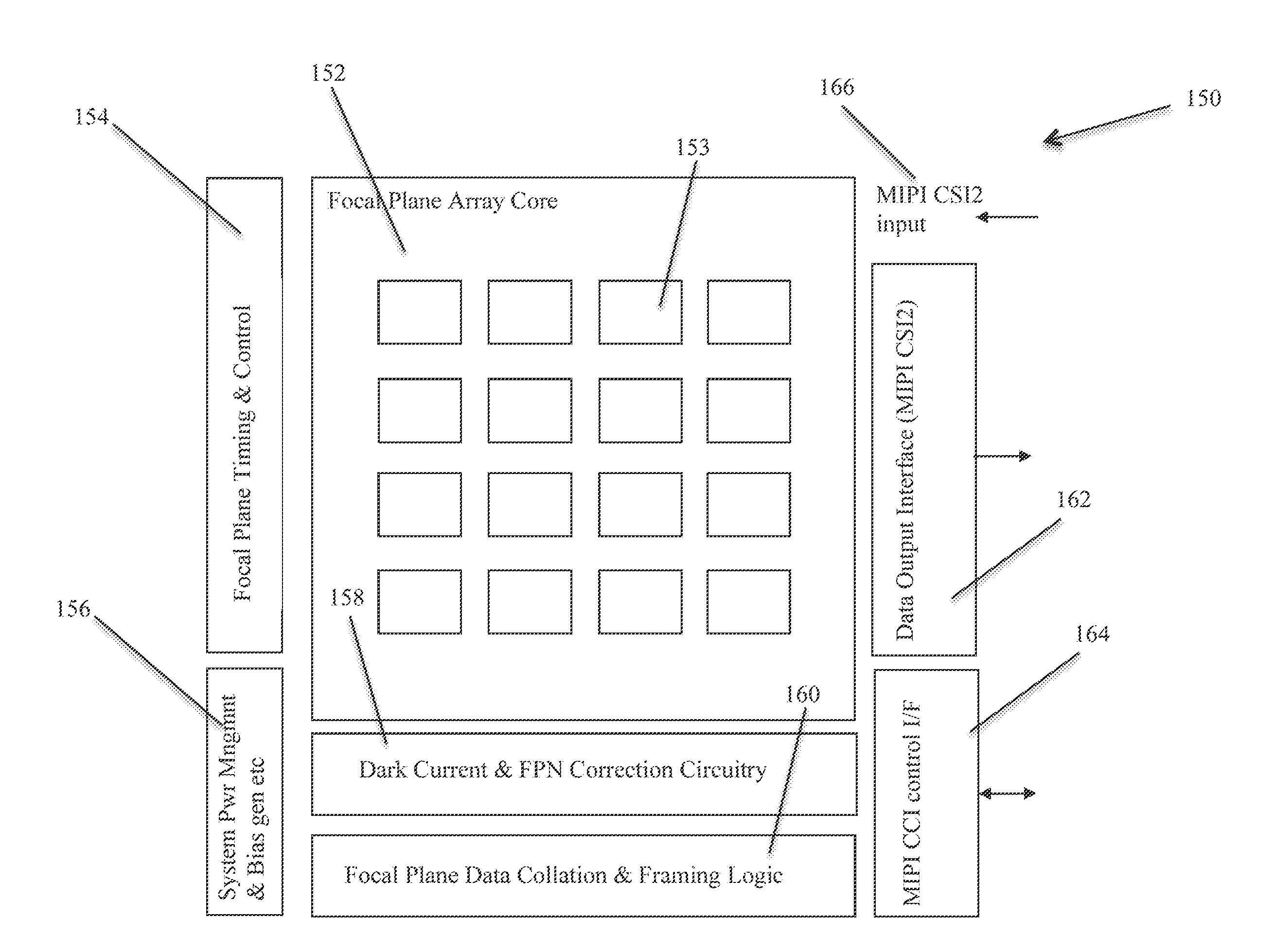
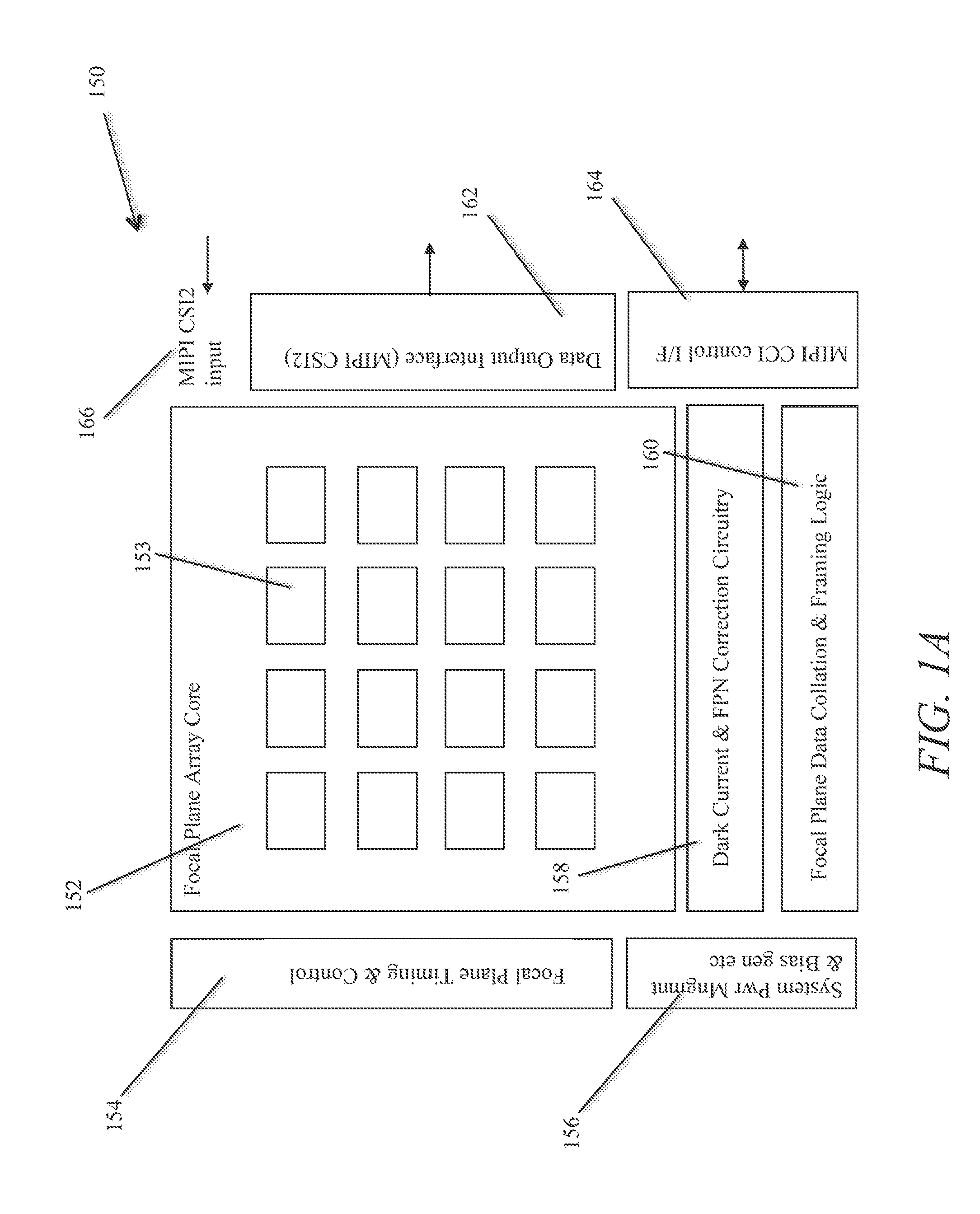
[0041]Turning now to the drawings, architectures for imager arrays configured for use in array cameras in accordance with embodiments of the invention are illustrated. In many embodiments, a centralized controller on a imager array enables fine control of the capture time of each focal plane in the array. The term focal plane describes a two dimensional arrangement of pixels. Focal planes in an imager array are typically non-overlapping (i.e. each focal plane is located within a separate region on the imager array). The term imager is used to describe the combination of a focal plane and the control circuitry that controls the capture of image information using the pixels within the focal plane. In a number of embodiments, the focal planes of the imager array can be separately triggered. In several embodiments, the focal planes of the imager array utilize different integration times tailored to the capture band of the pixels within each focal plane. The capture band of a pixel typic...


PUM


Abstract

Architectures for imager arrays configured for use in array cameras in accordance with embodiments of the invention are described. One embodiment of the invention includes a plurality of focal planes, where each focal plane comprises a two dimensional arrangement of pixels having at least two pixels in each dimension and each focal plane is contained within a region of the imager array that does not contain pixels from another focal plane, control circuitry configured to control the capture of image information by the pixels within the focal planes, where the control circuitry is configured so that the capture of image information by the pixels in at least two of the focal planes is separately controllable, sampling circuitry configured to convert pixel outputs into digital pixel data, and output interface circuitry configured to transmit pixel data via an output interface.

Description

RELATED APPLICATION[0001]This application claims priority to U.S. patent application Ser. No. 61 / 334,011 filed on May 12, 2010, which is incorporated by reference herein in its entirety.FIELD OF THE INVENTION[0002]The present invention relates generally to imagers and more specifically to imager arrays used in array cameras.BACKGROUND OF THE INVENTION[0003]A sensor used in a conventional single sensor camera, typically includes a row controller and one or more column read-out circuits. In the context of the array of pixels in an imager, the term “row” is typically used to refer to a group of pixels that share a common control line(s) and the term “column” is a group of pixels that share a common read-out line(s). A number of array camera designs have been proposed that use either an array of individual cameras / sensors or a lens array focused on a single focal plane sensor. When multiple separate cameras are used in the implementation of an array camera, each camera has a separate I / ...

Claims


Application Information

Patent Timeline
Patent Type & Authority Applications(United States)
IPC IPC(8): H04N5/335
CPCH04N9/045H04N5/345H04N5/3742H04N5/3653H04N5/3745H04N5/378H04N25/44H04N25/41H04N25/672H04N25/704H04N25/767H04N25/77H04N25/75H04N25/134H04N25/00H04N23/90H04N25/40H04N23/13H04N23/951H04N25/78H04N25/772
Inventor MCMAHON, ANDREW KENNETH JOHN
Owner FOTONATION LTD
Why Eureka
Try Eureka