System and method for robust calibration between a machine vision system and a robot

a machine vision system and robot technology, applied in the field of machine vision system calibration, can solve the problems of inability of end effectors to grasp workpieces, inability to accurately measure workpieces, inability to accurately assemble workpieces,

Active Publication Date: 2011-11-17
COGNEX CORP
View PDF42 Cites 140 Cited by
  • Summary
  • Abstract
  • Description
  • Claims
  • Application Information

AI Technical Summary

Benefits of technology

[0012]In an exemplary stationary camera environment, illustrative embodiment of the present invention illustratively imposes a constraint that there is a unique six degree of freedom transform (6 DOF) between each camera and the robot base coordinate system and explicitly imposes a constraint that there is a unique 6 DOF transform between the robot end effector and the calibration plate. It should be noted that in alternative embodiment of the present invention, a differing number of degrees of freedom may be utilized. As such, the description of 6 DOF should be taken as exemplary only. Illustrative embodiments of the present invention illustratively enable the simultaneous calibration of a plurality of cameras to a robot in addition to individual camera calibration, thereby obviated a need for first calibrating cameras to a workspace of a robot and then calibrating the machine vision system to the robot.

Problems solved by technology

A known disadvantage of utilizing such robots is that the workpiece must be presented at a known pose in order for the robot to successfully perform the task.
For example, the end effector may fail to grasp the workpiece if the workpiece is not initially located at the expected pose.
Workpiece pose inaccuracy is a well-known noted disadvantage of such robot systems and is a typical reason that robots are not selected for use in performing pick, place, and assembly operations.
A noted disadvantage of using machine vision to measure a workpiece's pose is that the machine vision system typically measures the workpiece pose with respect to the machine vision system's coordinate system, whereas the robot moves the end effector with respect to the robot's coordinate system.
Correspondingly, if the hand-eye calibration is inaccurate and does not reflect the true relationship between the machine vision system's coordinate system and the robot's coordinate system, then accurate machine vision measurement of the workpiece will not necessarily induce accurate end effector poses for picking, placing, and assembling the workpiece.
These inaccurate robot poses may result in the robot failing to perform the intended tasks.
In an exemplary case of a stationary camera environment, a noted disadvantage of Tsai and Lenz's technique is that it does not explicitly incorporate the constraint that there is one and only one pose of the camera with respect to the robot base and that there is one and only one pose of the calibration object with respect to the end effector.
Instead, Tsai and Lenz's technique allows for independent, therefore possibly inconsistent, estimates of the camera poses and further allows for independent, therefore possibly inconsistent, estimates of the calibration object poses.
A further noted disadvantage of Tsai and Lenz's technique is that it only performs calibration for a single camera in a machine vision system at a time.
This increases the time required to perform calibration and allows for independent and therefore possibly inconsistent calibration for individual cameras.
The drawback of both of these approaches (and all other approaches following the basic technique) is that they involve estimating differences between two rigid transforms: diff(Transform1,Transforms2), and there is no well-understood, physically-meaningful way of measuring the difference between two transforms.
Another drawback of methods like those described by Tsai & Lens and Strobl and Hirzinger is that estimating the hand-eye calibration based only on calibration plate poses is suboptimal.

Method used


Image

  • System and method for robust calibration between a machine vision system and a robot
  • System and method for robust calibration between a machine vision system and a robot
  • System and method for robust calibration between a machine vision system and a robot

Examples


Embodiment Construction

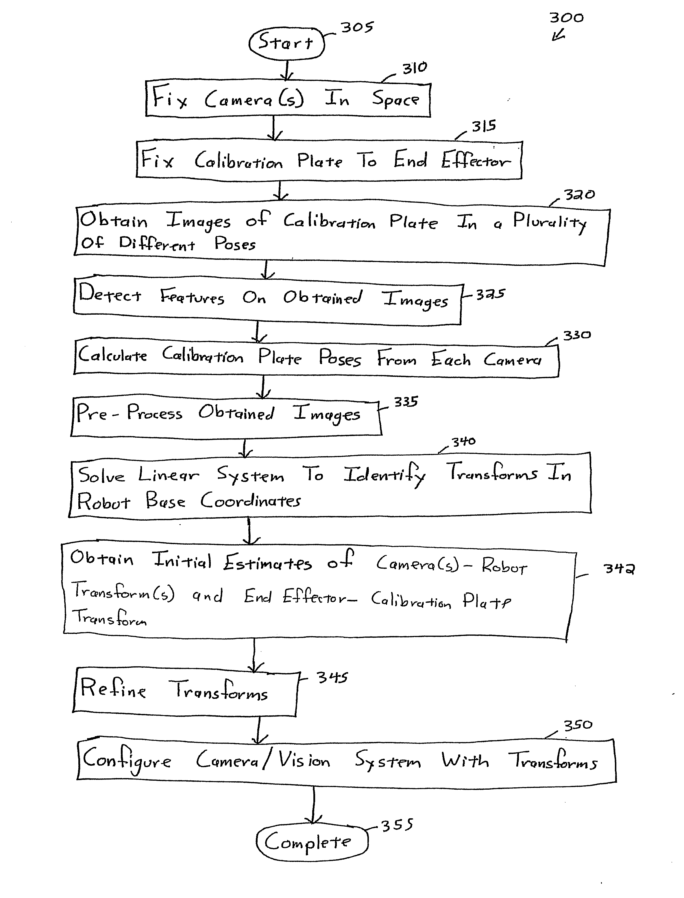
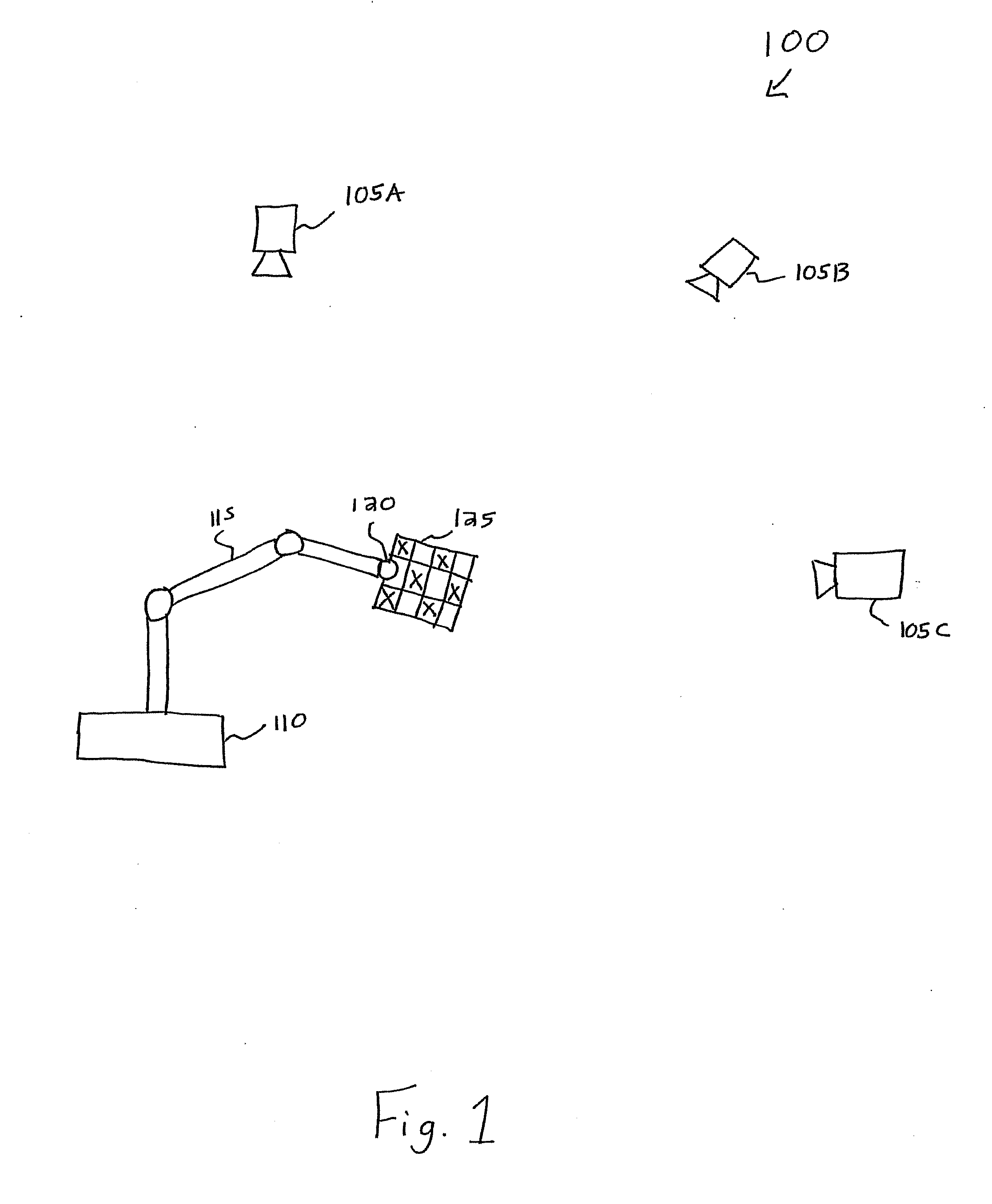
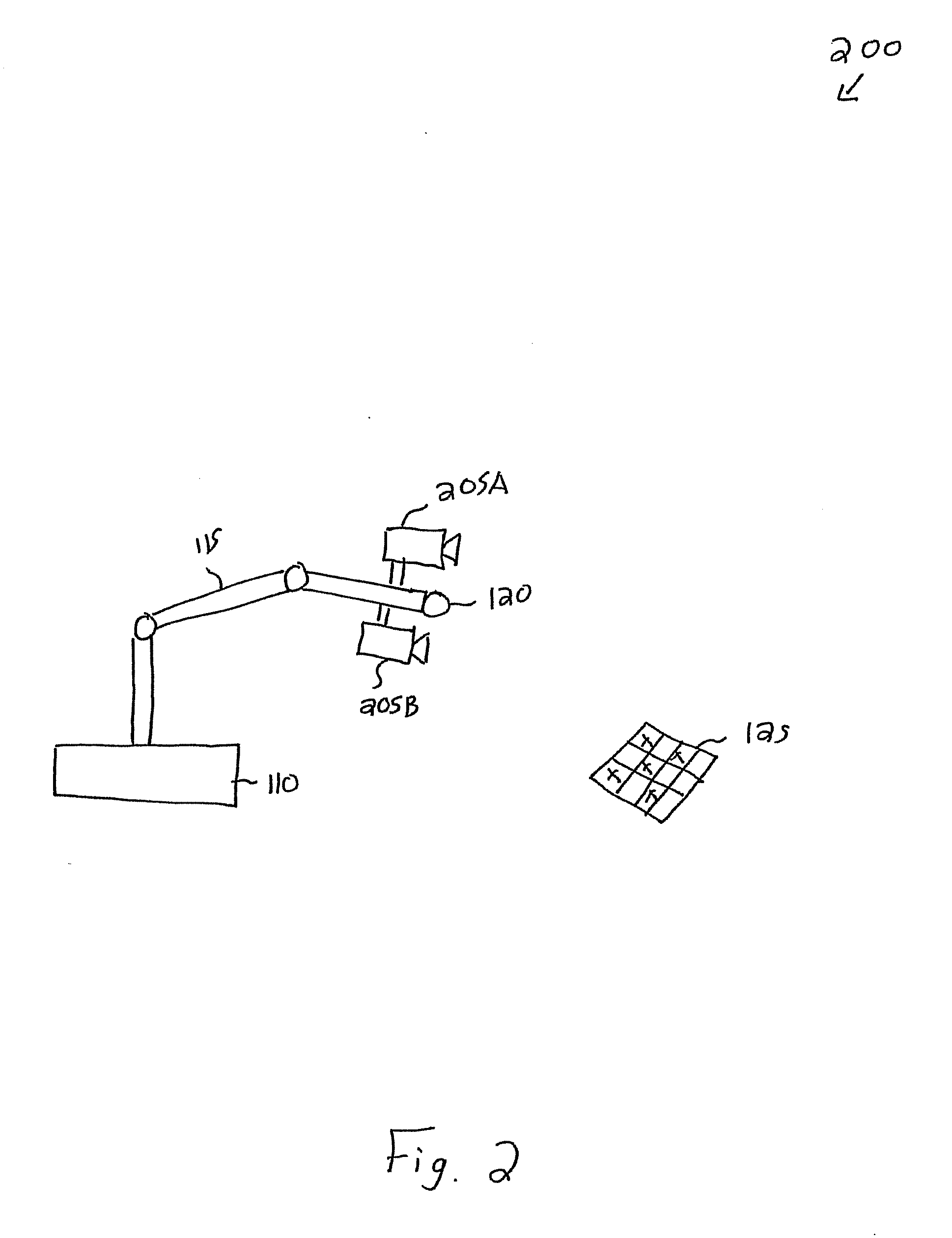
[0022]Illustrative embodiments of the present invention provide a system and method for accurately refining hand-eye calibration while illustratively imposing a constraint that there is a unique 6 DOF (degree of freedom) transform between each camera and the end effector for the moving camera case or imposing that there is a unique 6 DOF transform between each camera and the robot base for the stationary camera case. It should be noted that in alternative embodiment of the present invention, a differing number of degrees of freedom may be utilized. As such, the description of 6 DOF should be taken as exemplary only. Further, illustrative embodiments of the present invention illustratively enforce a constraint that there is a unique 6 DOF transform between the robot coordinate system and the calibration plate for the moving camera case. Alternatively, for the stationary camera case, illustrative embodiments of the present invention enforce a constraint that there is a unique 6 DOF tr...


PUM


Abstract

A system and method for robustly calibrating a vision system and a robot is provided. The system and method enables a plurality of cameras to be calibrated into a robot base coordinate system to enable a machine vision / robot control system to accurately identify the location of objects of interest within robot base coordinates.

Description

FIELD OF THE INVENTION[0001]Illustrative embodiment of the present invention relate to calibrating a machine vision system and, more particularly, to a system and method for calibration between a machine vision system and a robot.BACKGROUND OF THE INVENTION[0002]Articulated arms are controllable machines that can accurately and repeatably move an end effector throughout a workspace to a specified pose. As used herein, the term pose illustratively refers to a combination of three dimensional position and three dimensional rotation. A robot pose illustratively corresponds to the pose of the end effector in terms of the robot's coordinate system. Illustratively, end effectors are controllable machines that are capable of grasping and releasing workpieces and may comprise, e.g., mechanical grippers, vacuum suction, electromagnetic contacts, etc. Generally, as used herein, the combination of an articulated arm and an end effector is termed a robot. The three dimensional area that is acce...

Claims


Application Information

Patent Timeline
Patent Type & Authority Applications(United States)
IPC IPC(8): G06T7/00
CPCB25J9/1692B25J9/1697G05B2219/39008G06T7/0018G05B2219/39045G05B2219/39057G05B2219/39022G06T7/80Y10S901/09B25J9/1607
Inventor WALLACK, AARON S.LIU, LIFENGYE, XIANGYUN
Owner COGNEX CORP
Why Eureka
Try Eureka