Dynamic monitoring of mobile railway car undercarriage

Active Publication Date: 2011-11-17
GEOFORCE
View PDF12 Cites 80 Cited by
  • Summary
  • Abstract
  • Description
  • Claims
  • Application Information

AI Technical Summary

Problems solved by technology

These harsh conditions can include elevated temperatures

Method used


Image

  • Dynamic monitoring of mobile railway car undercarriage
  • Dynamic monitoring of mobile railway car undercarriage
  • Dynamic monitoring of mobile railway car undercarriage

Examples


Embodiment Construction

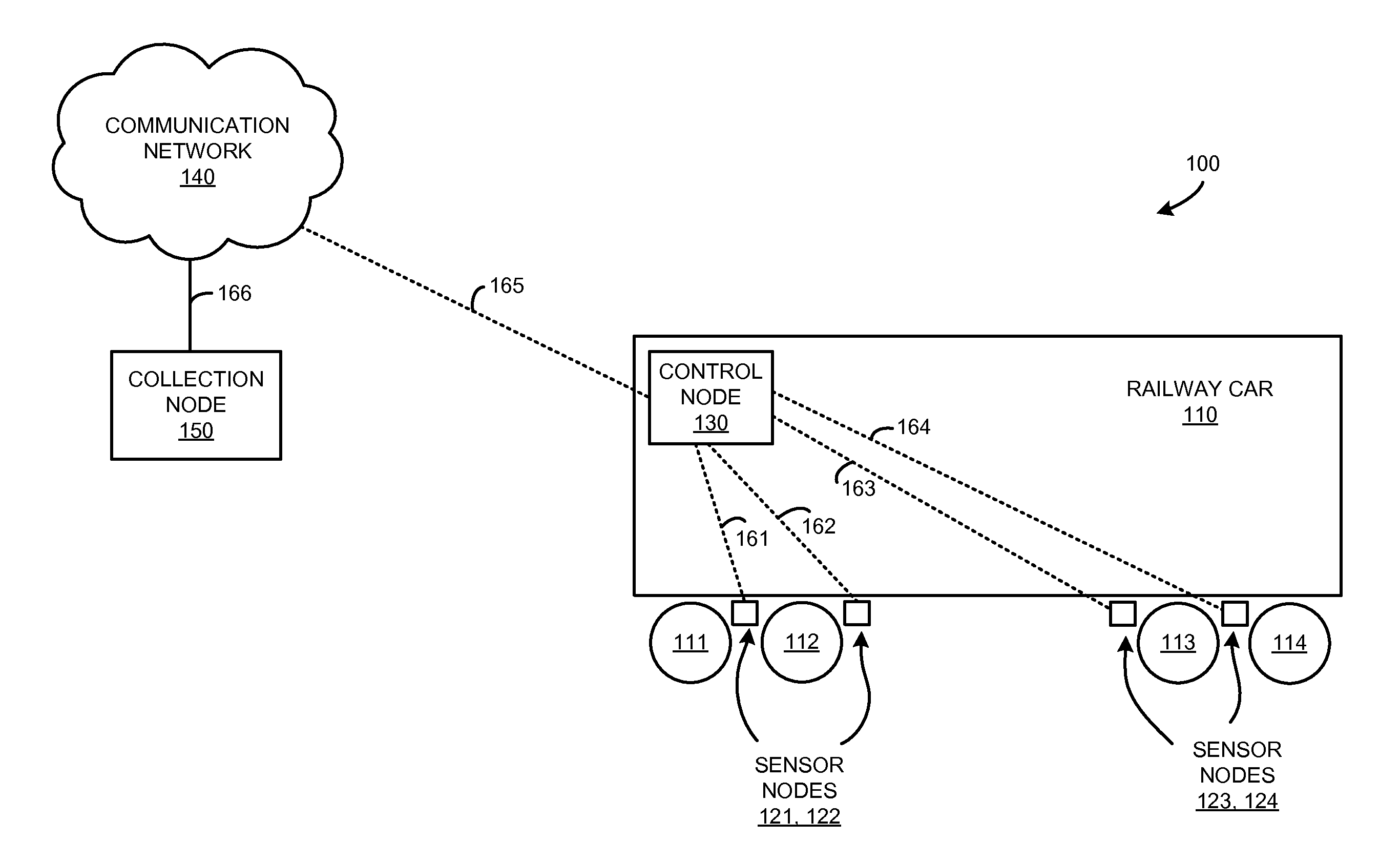
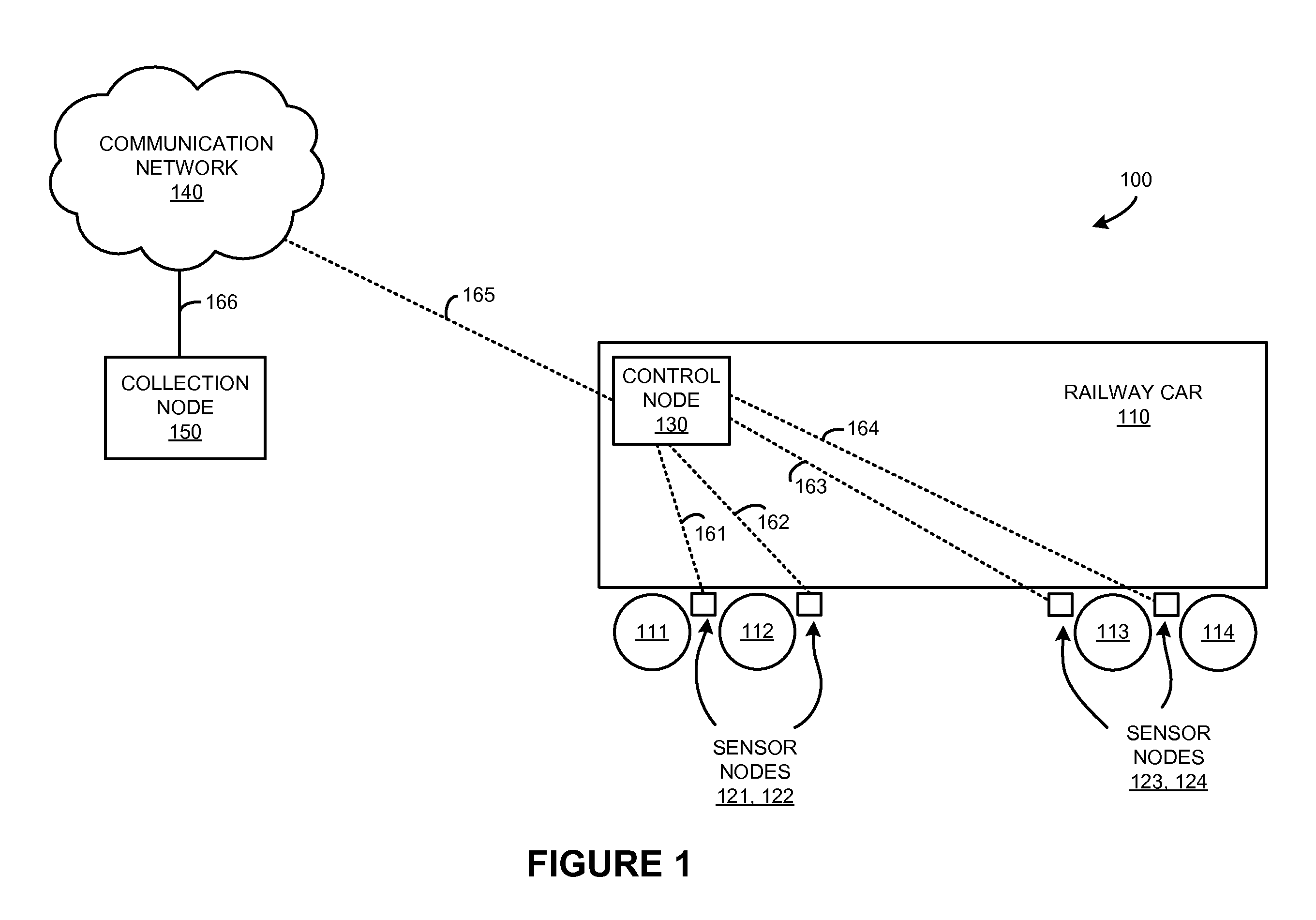
FIG. 1 is a system diagram illustrating railway car monitoring system 100. System 100 includes railway car 110, undercarriage elements 111-114 of railway car 110, sensor nodes 121-124, control node 130, communication network 140, and collection node 150. Control node 130 and each of sensor nodes 121-124 communicate over links 161-164, respectively. Control node 130 and communication network 140 communicate over wireless link 165. Communication network 130 and collection node 150 communicate over link 166. In this example, sensor node 121 is coupled to undercarriage element 111, sensor node 122 is coupled to undercarriage element 112, sensor node 123 is coupled to undercarriage element 113, and sensor node 124 is coupled to undercarriage element 114. It should be understood that although four sensor nodes and undercarriage elements are shown in FIG. 1, a different number of sensor nodes or undercarriage elements could be included.

Railway car 110 comprises a vehicle used on a rail tra...


PUM


Abstract

What is disclosed is a mobile railway car monitoring system. The mobile railway car monitoring system includes a plurality of sensor nodes coupled to an undercarriage portion of a railway car, and a control node coupled to the railway car. Each of the plurality of sensor nodes is configured to monitor the undercarriage portion of the railway car when in motion and transmit information about the undercarriage portion to the control node. The control node is configured to receive the information about the undercarriage portion, process the information to determine a fault condition for the undercarriage portion, and wirelessly report the fault condition to a collection system.

Description

TECHNICAL FIELDAspects of the disclosure are related to the field of vehicle monitoring devices, and in particular, railway car sensor systems.TECHNICAL BACKGROUNDRailway cars, such as those found in freight trains and passenger trains, include undercarriage portions to roll the railway car and an associated payload across railroad tracks. The undercarriage portion typically includes wheels and related equipment, such as axles, bearings, trucks, brakes, journals, gears, and other moving parts, which can experience harsh conditions while in use. These harsh conditions can include elevated temperatures while under heavy loads and during start / stop conditions. Stationary equipment, such as thermal imaging inspection equipment, or ‘hotbox’ detectors can be positioned at various points along a railroad track to take a snapshot of railway car bearing status. Stationary impact detectors can also be installed in the rails and used to detect wheel damage.OVERVIEWWhat is disclosed is a mobile...

Claims


Application Information

Patent Timeline
IPC IPC(8): G06F19/00H04Q5/22
CPCH04Q9/00B61K13/00H04Q2209/823H04Q2209/47H04Q2209/50H04Q2209/10
Inventor ARMITAGE, DAVID L.KUSHNIR, GREGORY FROIMMASON, MARK ALVINJOHNSON, JR., THEODORE CUTLER
Owner GEOFORCE
Why Eureka
Try Eureka