Submarine Renewable Energy Generation System Using Ocean Currents

a renewable energy and ocean current technology, applied in the direction of underwater equipment, vessel auxilary drives, special-purpose vessels, etc., can solve the problems of insufficient efficiency of current battery technology to allow the ship, increased risk of detection, and high nois

Inactive Publication Date: 2011-11-24
VLADIMIR MOLDOVANU & ASSOC
View PDF5 Cites 19 Cited by
  • Summary
  • Abstract
  • Description
  • Claims
  • Application Information

AI Technical Summary

Benefits of technology

[0011]The ship is also configured with extendable panels that serve

Problems solved by technology

However, current battery technology is not efficient enough to allow the ship to run at long intervals underwater (days.)
However, this method has several drawbacks.
First, while the diesel-powered ship is on the surface, it is more vulnerable to detection as it can be seen and it is extremely noisy.
Second, oper

Method used


Image

  • Submarine Renewable Energy Generation System Using Ocean Currents
  • Submarine Renewable Energy Generation System Using Ocean Currents
  • Submarine Renewable Energy Generation System Using Ocean Currents

Examples


Embodiment Construction

[0023]The various embodiments of the present invention and their advantages are best understood by referring to FIGS. 1A through 8 of the drawings. The elements of the drawings are not necessarily to scale, emphasis instead being placed upon clearly illustrating the principles of the invention. Throughout the drawings, like numerals are used for like and corresponding parts of the various drawings.

[0024]This invention may be provided in other specific forms and embodiments without departing from the essential characteristics as described herein. The embodiments described above are to be considered in all aspects as illustrative only and not restrictive in any manner. The following claims rather than the foregoing description indicate the scope of the invention.

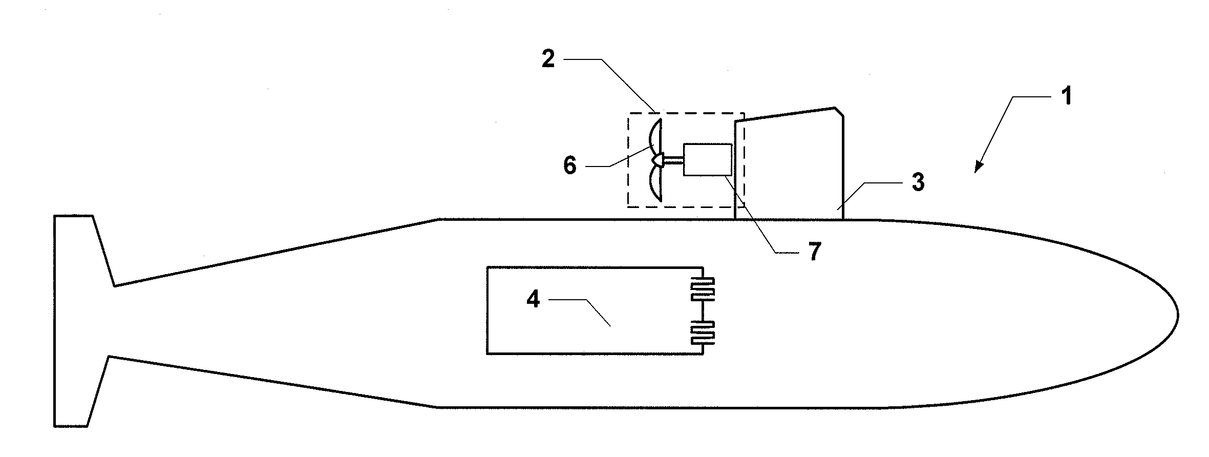
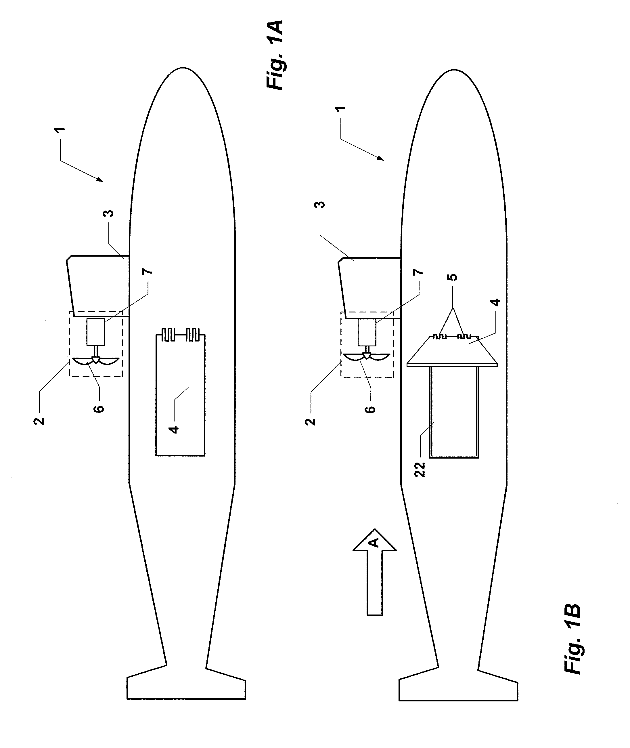
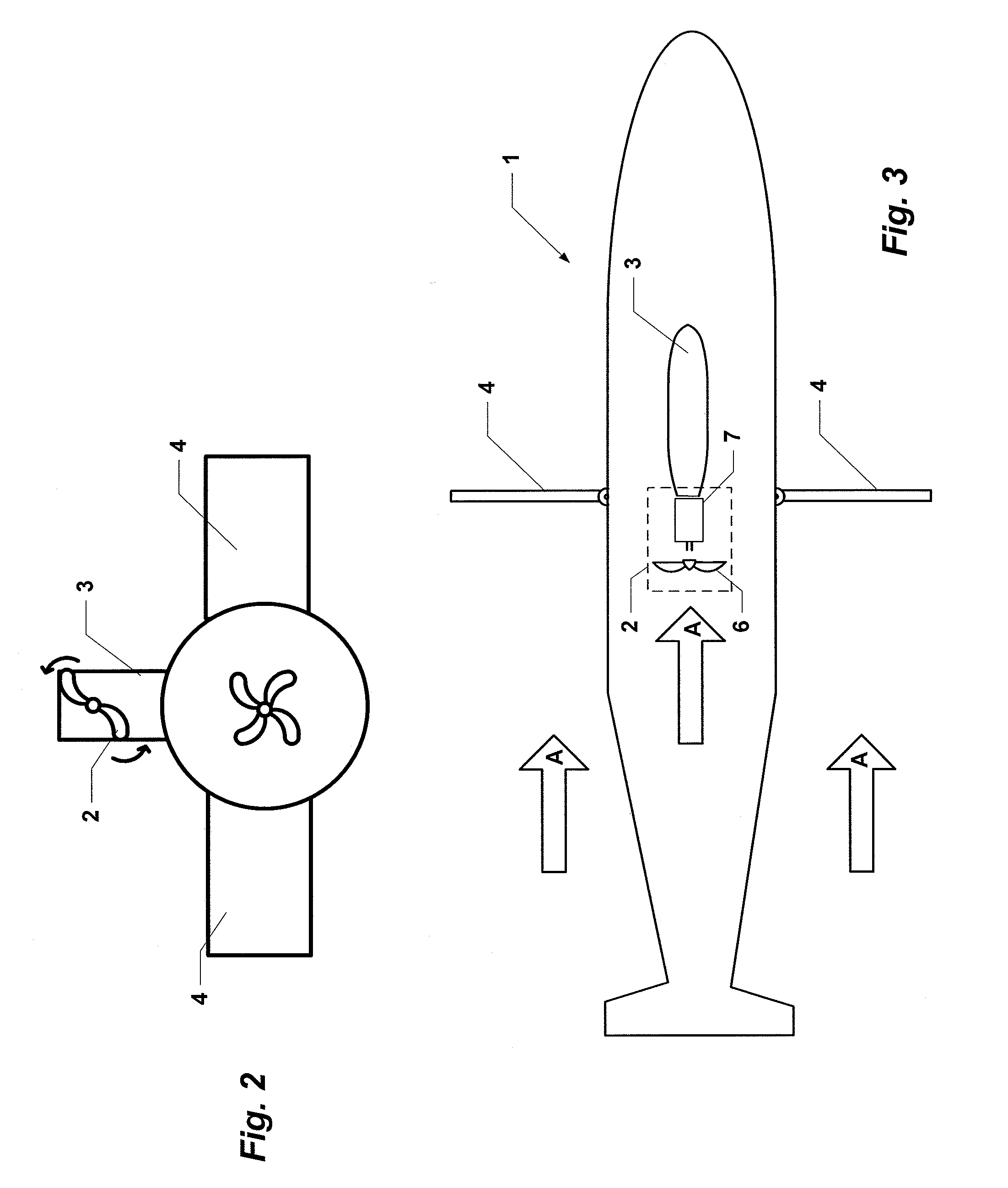
[0025]FIG. 1A depicts the starboard side of an exemplary submarine 1 having a turbine 2 mounted to the hull on the aft portion of the sail 3. The turbine 2 is comprised of a rotor 6 the rotation of which drives a generator 7. ...


PUM


Abstract

A system for generating electrical energy for a submarine using ocean currents includes a turbine mounted to the exterior hull that is comprised of a rotor, impelled by the ocean current and drives rotation of a generator for generating electrical energy. The submarine is configured with a pair of selectively extendable braking panels on either side of the submarine's hull.

Description

BACKGROUND[0001]1. Field[0002]The present invention relates generally to renewable, hydro-electric energy generation, and in particular to renewable hydro-electric energy generation for submarine ships.[0003]2. Description of the Problem and Related Art[0004]The power of moving water has long been harnessed and converted to other useful forms of energy, beginning with the water wheel. Water driven turbines have long been employed in dams to renewably generate electrical energy. Recently, sub-surface turbines have been developed to use ocean currents to generate electrical energy, for example, the “SeaGen” turbine, built by Marine Current Turbines, Ltd, of Bristol, United Kingdom. A further example, is that disclosed in U.S. patent application Ser. No. 11 / 998,593 by Kejha, which teaches an ocean current-powered, turbine anchored to the ocean floor. In these and other examples, it can be seen that efforts to convert ocean currents to energy have only been employed on stationary fixtur...

Claims


Application Information

Patent Timeline
IPC IPC(8): F03B13/10B63G8/00
CPCB63G8/00B63J3/04B63J2003/046F03B13/10Y02E10/28F05B2240/931Y02E10/22Y02T70/70F03B17/061Y02E10/20Y02T70/00Y02E10/30
Inventor MOLDOVANU, VLADIMIRMCCOY, JR., JAMES RICHARD
Owner VLADIMIR MOLDOVANU & ASSOC
Why Eureka
Try Eureka