Method and apparatus of manufacturing functionally gradient material

a technology of functional gradients and gradients, applied in the direction of coatings, chemistry apparatus and processes, printed circuit aspects, etc., can solve the problems of failing to teach functional materials in which properties, or the like, gradually change continuously or in a stepwise fashion

Inactive Publication Date: 2011-11-24
FUJIFILM CORP
View PDF3 Cites 5 Cited by
  • Summary
  • Abstract
  • Description
  • Claims
  • Application Information

AI Technical Summary

Benefits of technology

[0016]According to the present invention, the ratio between the volume of a first functional ink ejected from a first inkjet head and the volume of a second functional ink ejected from a second inkjet head is specified, a plurality of layers are superimposed onto a base material by repeating a step of forming one layer by ejecting inks in accordance with the specified ratio, and the respective layers of the plurality of layers progressively have a smaller ratio of the first functional ink and a larger ratio of the second functional ink, toward the upper layer; therefore, it is possible to manufacture a functionally gradient material using inkjet technology.

Problems solved by technology

However, Japanese Patent Application Publication No. 2007-88221 fails to teach functional materials in which properties, or the like, gradually change continuously or in a stepwise fashion.

Method used


Image

  • Method and apparatus of manufacturing functionally gradient material
  • Method and apparatus of manufacturing functionally gradient material
  • Method and apparatus of manufacturing functionally gradient material

Examples


first embodiment

Configuration of Bump Forming Apparatus

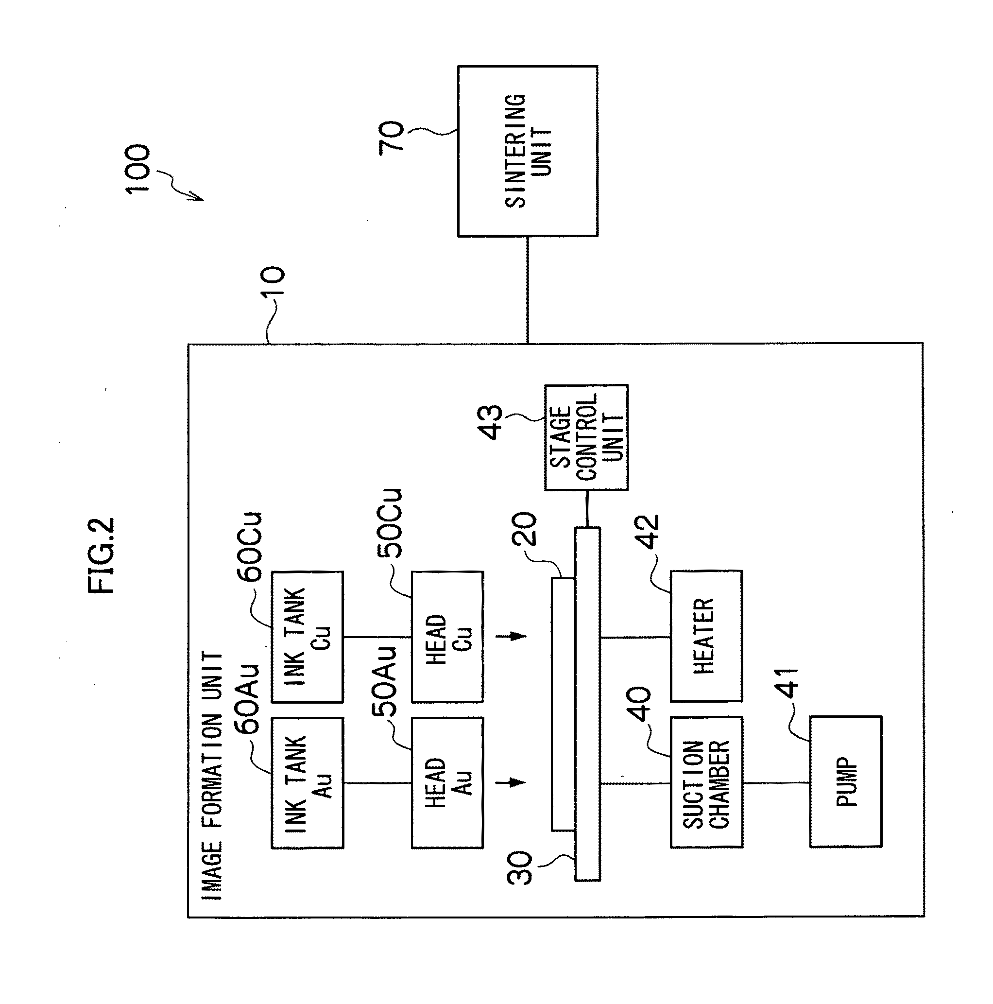
[0042]FIG. 2 is a general schematic diagram of a bump forming apparatus 100 relating to a first embodiment, and FIG. 3 is a schematic drawing of an image formation unit 10 of the bump forming apparatus 100. As shown in FIGS. 2 and 3, the bump forming apparatus 100 has an image formation unit 10 and a sintering unit 70, and the image formation unit 10 employs a flat head type inkjet image forming apparatus. More specifically, the image formation unit 10 includes a stage 30 on which an IC wafer 20 forming a base material is loaded, a suction chamber 40 for holding the IC wafer 20 loaded on the stage 30, by suction, and inkjet head 50Au and inkjet head 50Cu which eject respective inks onto the IC wafer 20.

[0043]The IC wafer 20 is a plate-shaped member that is made of silicon and has a substantially circular planar shape, and a plurality of IC chips 21 (not illustrated in FIG. 2 and FIG. 3) are formed on the surface of the IC wafer 20.

[0044]The sta...

second embodiment

[0098]Next, a second embodiment of the present invention will be described. The description given below does not explain the composition which is the same as or similar to that of the first embodiment described above. In the first embodiment, each layer of a bump which is a functionally gradient material are formed by an image formation mixing method which ejects a plurality of pure inks and diffuses and mixes the inks together by image formation, but in the second embodiment, each layer is formed by ejecting mixed inks which are diffused and mixed in advance.

Composition of Bump Forming Apparatus

[0099]FIG. 7 is a general schematic drawing of a bump forming apparatus 101 relating to a second embodiment. As shown in FIG. 7, the bump forming apparatus 101 relating to the present embodiment includes an image formation unit 11, and the image formation unit 11 includes ink tanks 60-1 to 60-5 which store inks of five types, and inkjet heads 50-1 to 50-5 to which inks are supplied from the ...

modification examples

Other Modification Examples

[0227]FIGS. 20A and 20B are illustrative diagrams of a mode where, when generating a functionally gradient material using components of two types, the component having a smaller volume ratio (Au nano-particle ink) is applied first and the component having a larger volume ratio is applied subsequently.

[0228]The dots 24-2-Au-1 indicated by the diagonal hatching in FIG. 20A are dots formed by Au nano-particle ink which is applied first. On the other hand, the dots 24-2-Cu-1 indicated by the broken line are virtual dots formed by Cu nano-particle ink that is to be applied after applying the Au nano-particle ink.

[0229]The volume ratio of the Au nano-particle ink to Cu nano-particle ink is 2:8, and the numerical quantity ratio between the dots 24-2-Au-1 formed by Au nano-particle ink and the dots 24-2-Cu-1 formed by Cu nano-particle ink is specified by this ratio.

[0230]Although not illustrated, dots 24-2-Cu-1 made by Cu nano-particle ink are formed at the same d...


PUM

PropertyMeasurementUnit
thicknessaaaaaaaaaa
temperatureaaaaaaaaaa

Abstract

A method of manufacturing a functionally gradient material having a gradient from a first material to a second material different to the first material by ejecting inks onto a base material from a plurality of inkjet heads, includes the steps of: supplying a first functional ink containing the first material to a first inkjet head; supplying a second functional ink containing the second material to a second inkjet head; specifying a ratio between a volume of the first functional ink ejected from the first inkjet head and a volume of the second functional ink ejected from the second inkjet head; causing the first inkjet head to eject the first functional ink and/or causing the second inkjet head to eject the second functional ink, in accordance with the specified ratio, so as to form one layer; and stacking a plurality of layers onto the base material by repeating the forming step, so as to obtain a laminated body, wherein in the control step, the ratio between the first functional ink and the second functional ink is specified in such a manner that respective layers of the plurality of layers progressively have a smaller ratio of the first functional ink and a larger ratio of the second functional ink, toward an upper layer.

Description

BACKGROUND OF THE INVENTION[0001]1. Field of the Invention[0002]The present invention relates to a method and an apparatus of manufacturing a functionally gradient material, and more particularly, to technology for manufacturing a functionally gradient material using inkjet technology.[0003]2. Description of the Related Art[0004]An inkjet recording apparatus is known which forms an image on a recording medium by ejecting ink droplets from nozzles so as to deposit the ejected droplets on a recording medium, such as paper, by means of actuators of piezo elements. In recent years, the nozzle arrangement pitch in inkjet recording apparatuses has increased in density and it has also become possible to eject very small ink droplets of several pl (pico-liter), which means that recording of high-resolution images has become possible.[0005]Techniques for using an inkjet apparatus of this kind in applications other than image recording have been proposed.[0006]For example, Japanese Patent App...

Claims


Application Information

Patent Timeline
Patent Type & Authority Applications(United States)
IPC IPC(8): B32B38/14B05C5/02
CPCH01L24/11H01L2224/16225H01L2224/11505H01L2224/16227H01L2224/73204H01L2924/01029H01L2924/01047H01L2924/01079H05K3/125H05K3/4007H05K2201/0367H05K2203/0285H05K2203/1476H01L2924/01005H01L2924/01006H01L2924/01024H01L2924/01033H01L2924/01072H01L2924/01078H01L2924/14H01L2224/11312H01L2224/13144H01L2224/13147H01L2224/11013H01L24/13H01L2224/32225H01L2224/94H01L2224/11848H01L24/742H01L2224/11H01L2924/00012H01L2224/05647H01L2224/11332H01L2224/11901H01L2224/1308H01L2924/15787H01L2924/181H01L2924/00H01L2924/00014
Inventor KATSUMURA, MANABU
Owner FUJIFILM CORP
Why Eureka
Try Eureka