Seal assembly with shroud

Active Publication Date: 2011-11-24
MOYNO
View PDF5 Cites 2 Cited by
  • Summary
  • Abstract
  • Description
  • Claims
  • Application Information

AI Technical Summary

Benefits of technology

In one embodiment the present invention is an improved, robust seal assembly. More particularly, in one embodiment the present invention is a seal system including a sleeve configured to receive a rotatable shaft therein and a dynamic race configured to be rotatably coupled to the shaft. The seal system further includes a biasing element configured to urge the dynamic race into engagem

Problems solved by technology

However, the material being processed can be under high pressure and can be trapped in or otherwise interfere with proper operation and sealing of the seal assemblies.

Method used


Image

  • Seal assembly with shroud
  • Seal assembly with shroud
  • Seal assembly with shroud

Examples


Embodiment Construction

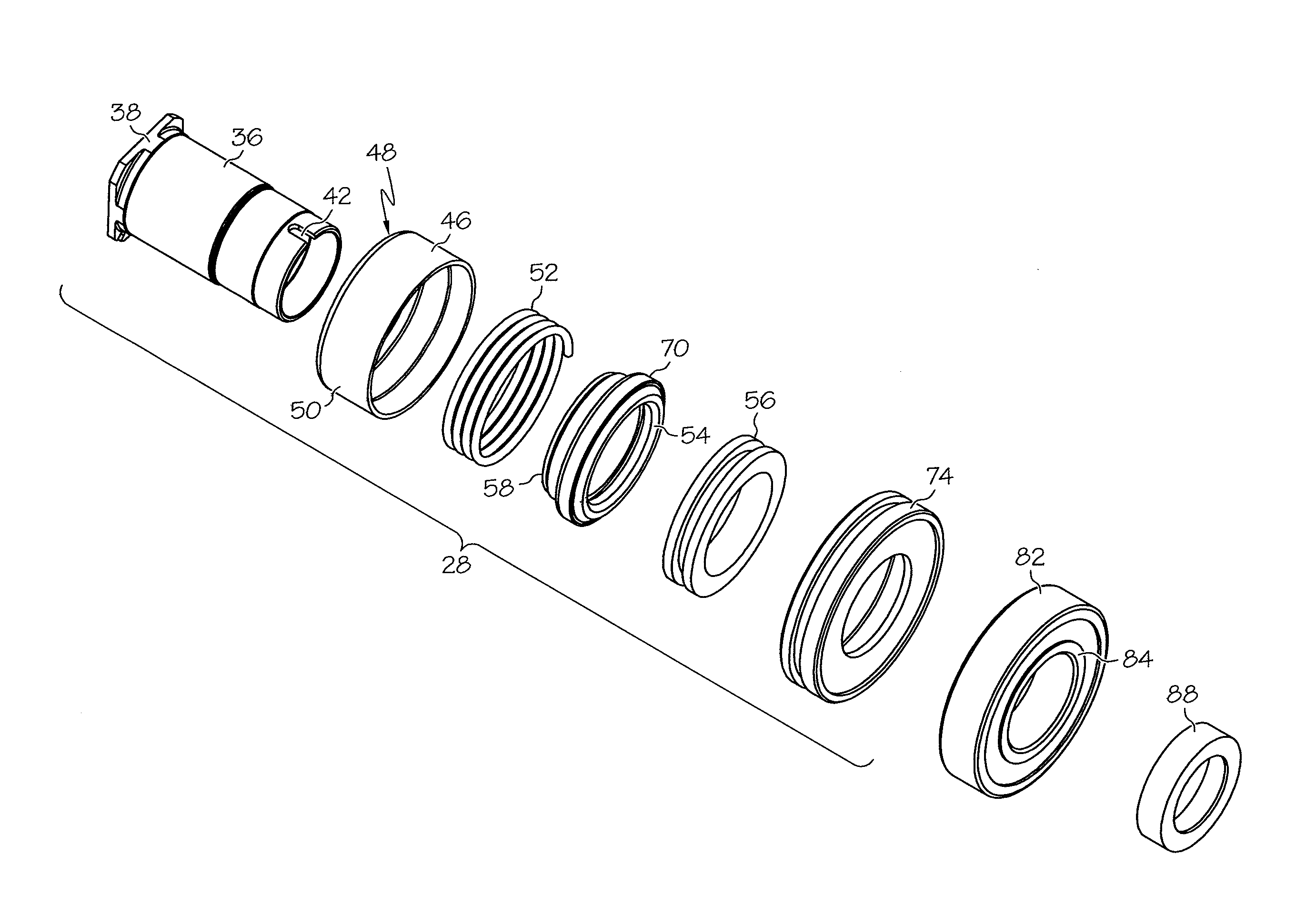
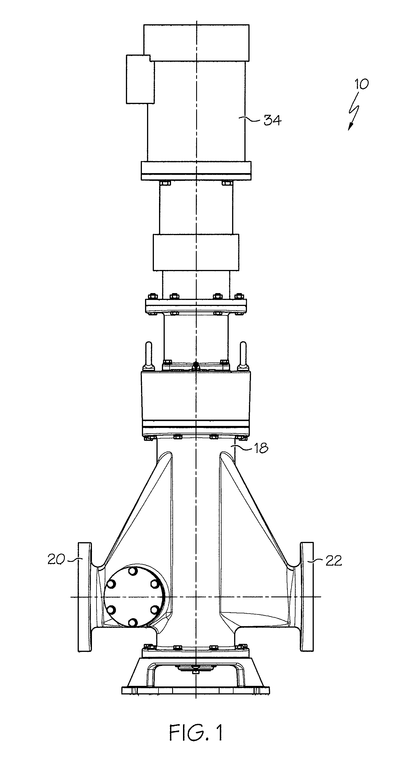
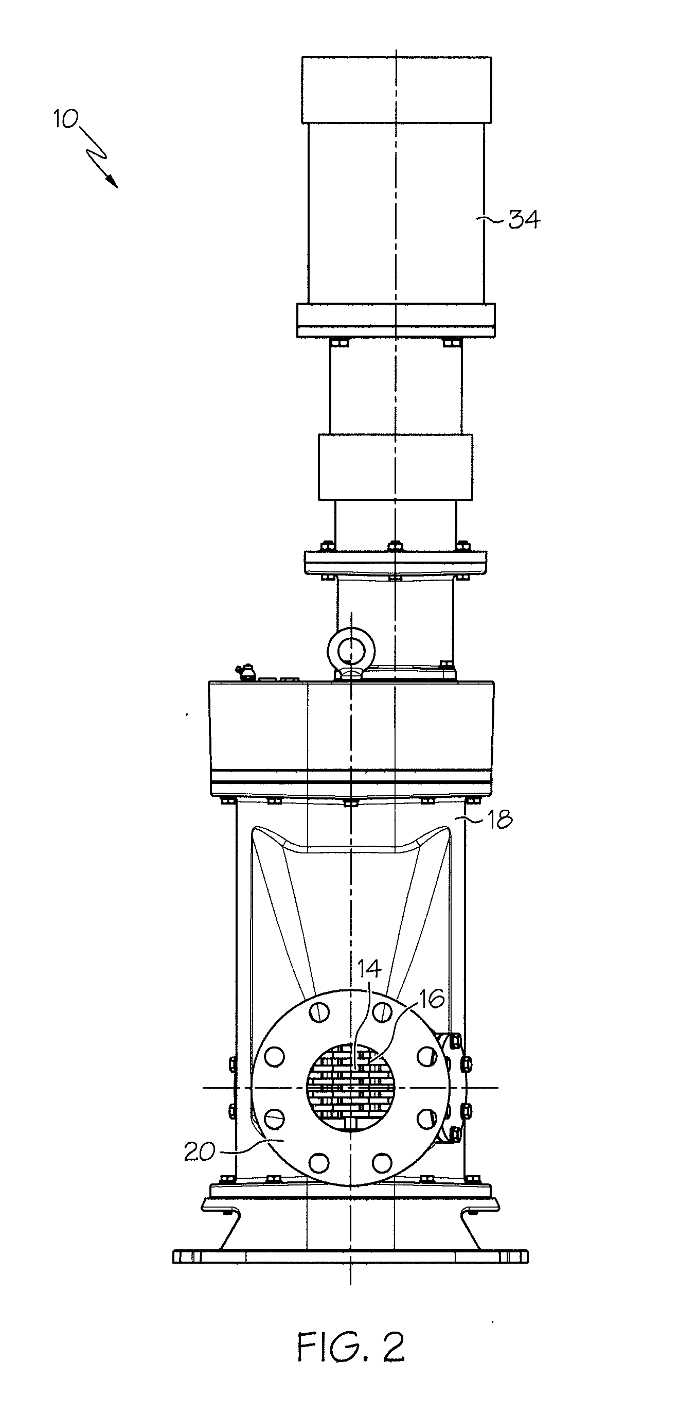
FIGS. 1-4 illustrate a grinder assembly / comminutor 10 in which a seal assembly disclosed herein may be utilized. However, it should be understood that the seal assembly can be used in any of a wide variety of systems or components in which it is desired to seal and / or journal a rotating shaft, such as such as wastewater treatment systems, food processing equipment, materials handling systems and the like which can carry any of a variety of elements (if any) on the shafts such as cutters, spacers, baffles, diverters, agitators, mixing elements, screens, augers, pumping elements or the like. For example, besides being used in a grinder assembly the seal assembly can be used to journal a shaft carrying a cylindrical screen which is configured to screen or divert solids suspended in a liquid stream; to journal a shaft of a progressing cavity pump; to journal a shaft of an auger, etc.

The grinder assembly 10 shown in FIGS. 1-4 includes a pair of parallel rotatable shafts 12 (shown as shaf...


PUM

PropertyMeasurementUnit
Lengthaaaaaaaaaa
Pressureaaaaaaaaaa
Flow rateaaaaaaaaaa

Abstract

A seal system including a sleeve configured to receive a rotatable shaft therein and a dynamic race configured to be rotatably coupled to the shaft. The seal system further includes a biasing element configured to urge the dynamic race into engagement with a static race to form a primary seal, and a shroud configured to be rotatably coupled to the sleeve and positioned radially outside the biasing element. The seal system also includes a sealing element configured to be positioned radially inside the biasing element and to sealingly engage the sleeve to provide a secondary seal to generally block fluid bypassing the primary seal.

Description

The present invention is directed to a seal assembly for use with a rotatable component, and, more particularly, to a seal assembly including a shroud.BACKGROUNDSeal assemblies are often utilized to journal the ends of a rotating shaft in a sealed manner. Such seal assemblies may be used in fluids processing technologies, such as wastewater treatment, food processing, materials handling and the like in which a rotatable shaft is utilized to carry cutters, spacers, baffles, diverters, agitators, mixers, pumping elements, etc. In many applications, it is desired to isolate the material being processed. However, the material being processed can be under high pressure and can be trapped in or otherwise interfere with proper operation and sealing of the seal assemblies.SUMMARYIn one embodiment the present invention is an improved, robust seal assembly. More particularly, in one embodiment the present invention is a seal system including a sleeve configured to receive a rotatable shaft th...

Claims


Application Information

Patent Timeline
IPC IPC(8): B02C7/12B23P11/00F16J15/38F16J15/16F16J15/34
CPCB02C18/142Y10T29/49826F16J15/348B02C18/16
Inventor AMBURGEY, MICHAEL DUANE
Owner MOYNO
Why Eureka
Try Eureka