Sealing joint with integrated mating surface

Inactive Publication Date: 2011-11-24
AIRCELLE
View PDF13 Cites 2 Cited by
  • Summary
  • Abstract
  • Description
  • Claims
  • Application Information

AI Technical Summary

Benefits of technology

[0022]An arrangement such as this makes it possible to minimize the area of contact between the mating surface and the second duct, the two being liable to move relative to one another.
[0024]Moreover, it will be noted that the reinforcing plate is located at the mating surface. It does not therefore impair the overall flexibility of the seal and does not influence the compression forces.
[0025]In this way, the skirt of the seal no longer comes into direct contact with the mating surface of the second duct but is protected by the reinforcing plate which has better resistance to wear.
[0033]Advantageously, the reinforcement has a perforated surface. This minimizes the mass of the reinforcement and therefore the additional mass of the seal according to the invention, by comparison with a seal of the prior art.
[0034]Advantageously, the reinforcement has an external peripheral edge that is flanged or locally stiffened. A feature such as this improves the overall stiffness of the reinforcement and thus makes it possible to minimize the deformation thereof, notably in the event of fire, and therefore to avoid any leaks at its mating face.

Problems solved by technology

Furthermore, when the seal is subjected to a compressive force, the central part, also known as the skirt, will naturally have a tendency to become compressed and to form rolls which could protrude beyond the overall space of the seal and come into contact with the second duct or with some other surface.
This is not desirable because relative movements would then carry the risk of causing damage to the skirt, and not just the mating surface.

Method used


Image

  • Sealing joint with integrated mating surface
  • Sealing joint with integrated mating surface
  • Sealing joint with integrated mating surface

Examples


Embodiment Construction

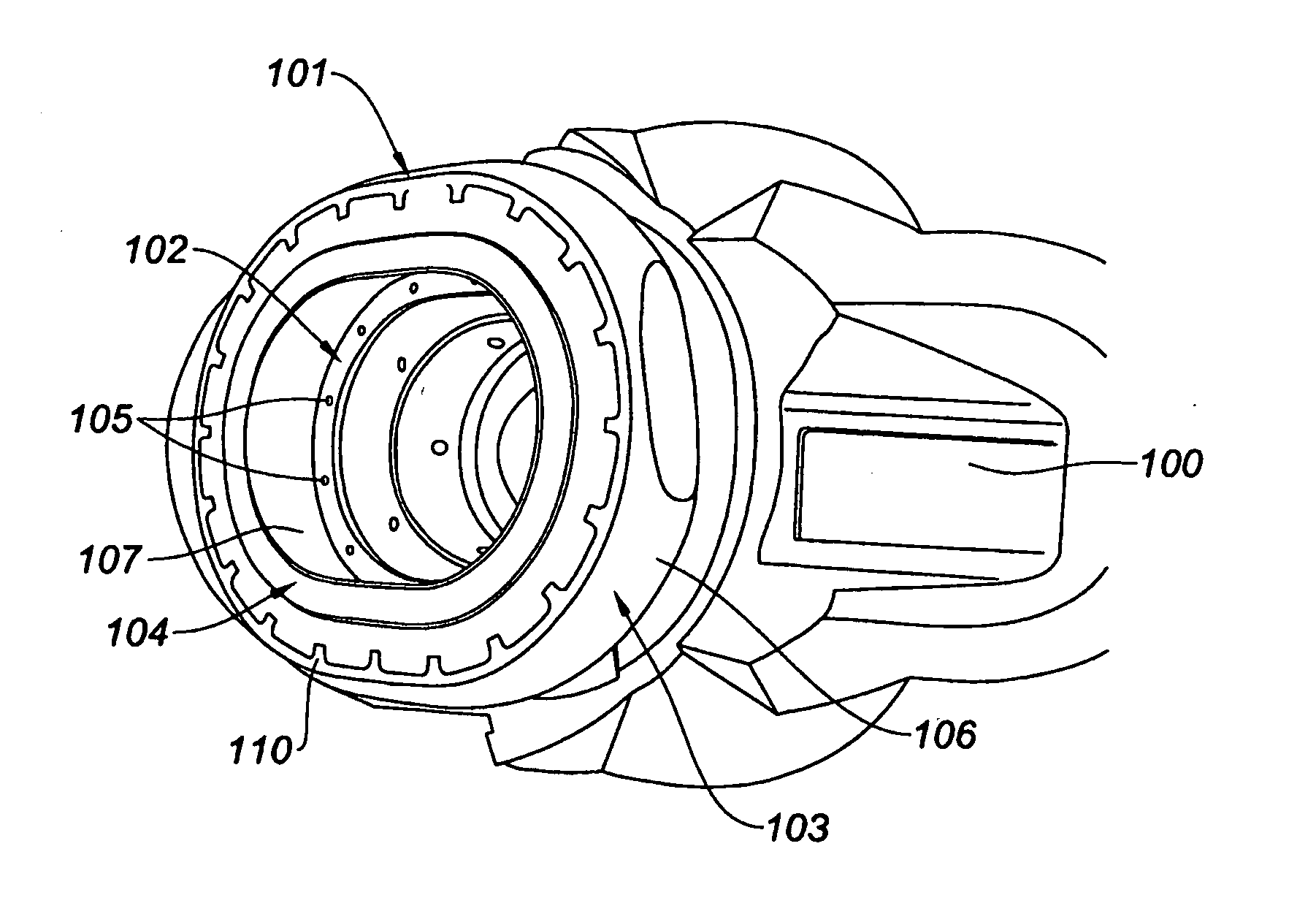
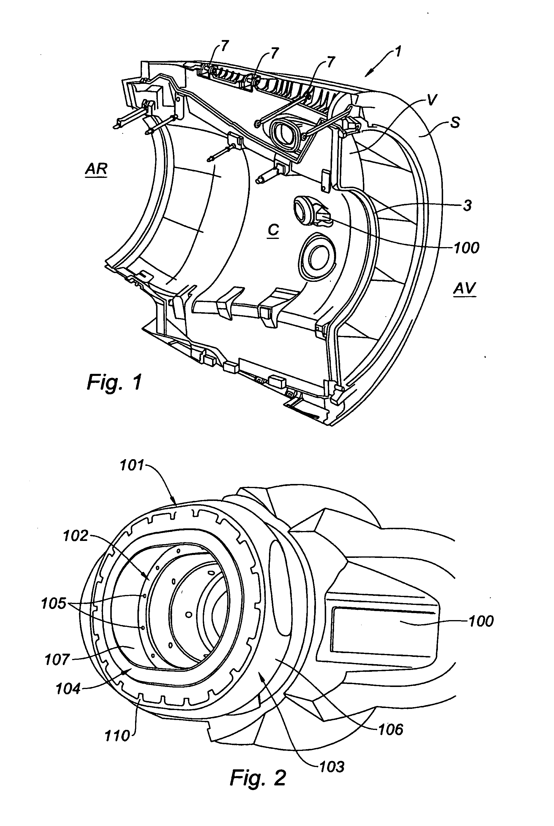
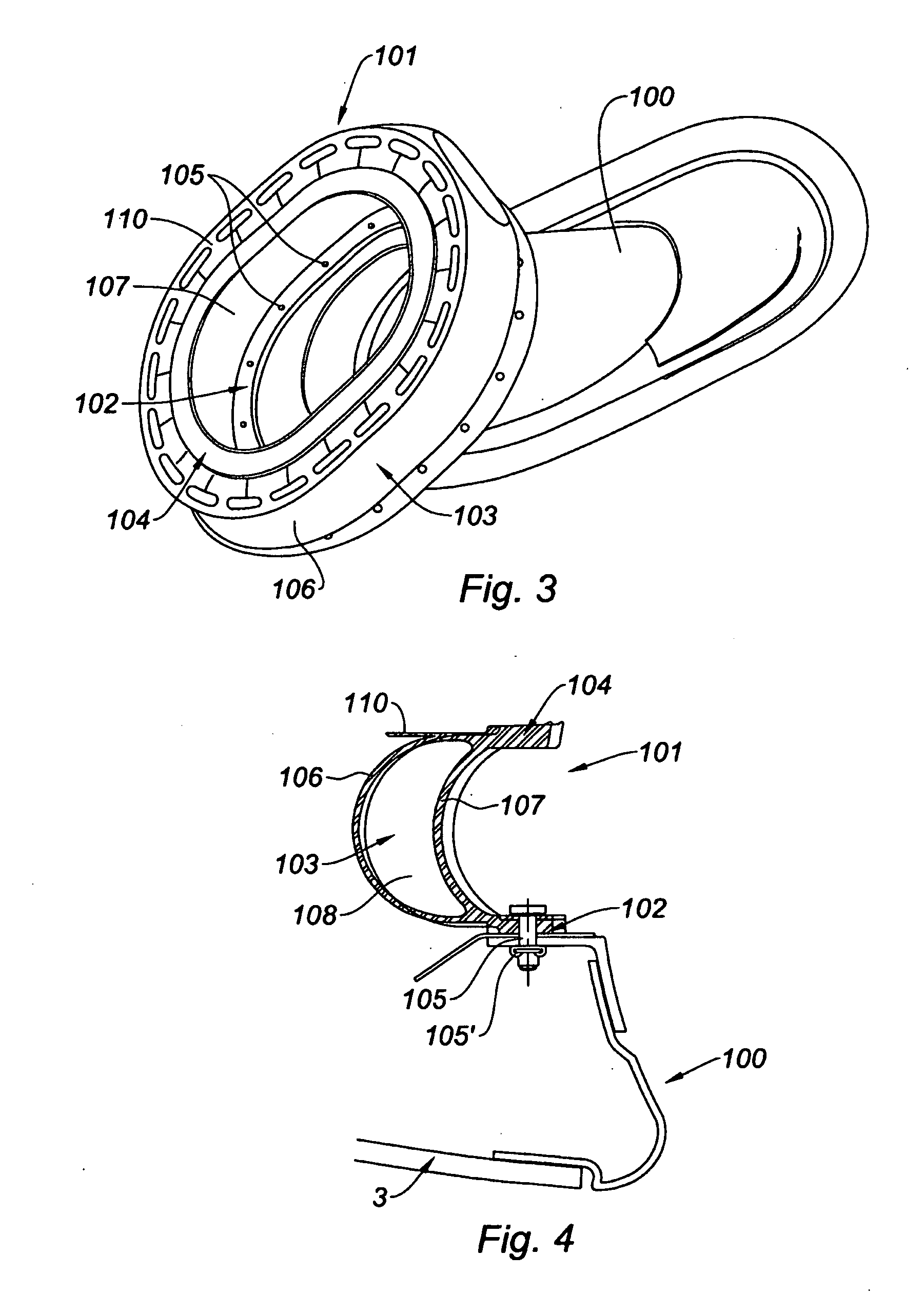
[0043]Reference is made to FIG. 1 which shows a nacelle right-hand half-shell 1 which in this instance is intended to be positioned at the rear of a nacelle and, with a second half-shell, constitutes a nacelle rear structure able to surround a rear part of a turbojet engine. It must be noted that this rear structure may incorporate thrust-reversal means, it being understood that the invention also applies to the case of a plain nacelle, that is to say one that has no thrust-reversal means.

[0044]The references AV and AR respectively denote the front and rear parts of the half-shell 1, with respect to the direction of the flow of air intended to flow within this half-shell 1.

[0045]In this particular instance, this half-shell 1 comprises an internal half-structure 3, defining a half-cavity C intended to accommodate a turbojet engine (not depicted).

[0046]This half-shell 1 also comprises an outer structure 5 defining, with the inner structure 3, a half-flow-path V intended to have passin...


PUM


Abstract

The invention relates to a sealing joint (101) designed to be arranged between a first duct (100) and a second duct which are susceptible to relative axial and / or radial movements, yet belonging to the same fluid distribution circuit, said joint comprising a flexible central part (103) with a generally cylindrical shape matching the form of the first and second ducts and made from material resistant to said fluid, having a mounting surface (102) for fixing to the first duct on one side and a mating surface (104) on the other side for making contact with the second duct such as to provide a flexible sealing connection between the first and second duct, characterised in that the mating surface has a peripheral reinforcement (110) extending radially at least partly above the central part.

Description

TECHNICAL FIELD[0001]The invention relates to a seal intended to be fitted between two duct elements liable to undergo relative movement in a nacelle for a turbojet engine.BACKGROUND[0002]An aircraft is propelled by a number of turbojet engines each housed in a nacelle; each nacelle also houses a collection of ancillary devices associated with the operation thereof and performing various functions when the turbojet engine is operating or stationary.[0003]A nacelle generally has a tubular structure comprising an air intake forward of a turbojet engine, a middle section intended to surround a fan of the turbojet engine, a rear section that may house thrust-reversal means and is intended to surround the combustion chamber of the turbojet engine, and a jet pipe, the outlet of which is situated downstream of the turbojet engine.[0004]Modern nacelles are often intended to house a bypass turbojet engine capable, via the blades of the rotating fan, of generating a flow of hot air (also know...

Claims


Application Information

Patent Timeline
IPC IPC(8): F16J15/02
CPCF16L27/108B64D29/00
Inventor BUNEL, SERGE
Owner AIRCELLE
Why Eureka
Try Eureka