
Dual force mode fine stage apparatus

a technology of fine stage and force mode, which is applied in the direction of photomechanical equipment, instruments, printing, etc., can solve the problems of increasing the size of the actuator that acts between the coarse stage and the fine stage, sacrificing accuracy, and affecting the accuracy so as to achieve the effect of meeting throughput requirements, reducing the size and mass of the overall stage, and sacrificing accuracy

Inactive Publication Date: 2006-01-24
NIKON CORP
View PDF9 Cites 10 Cited by
  • Summary
  • Abstract
  • Description
  • Claims
  • Application Information

AI Technical Summary

Benefits of technology

The present invention relates to a scanning apparatus that can accurately control the position of an object along a first axis. The apparatus includes a coarse stage and a fine stage, and a coupler that connects the two stages. The coupler has two ends and is designed to allow for high or low transmissibility between the coarse and fine stages depending on the direction of movement. The apparatus can be controlled using a single actuator or two actuators, and can be used for scanning a reticle or other objects. The technical effects of the invention include a smaller size of the overall stage, reduced power consumption, and improved accuracy and throughput requirements.

Problems solved by technology

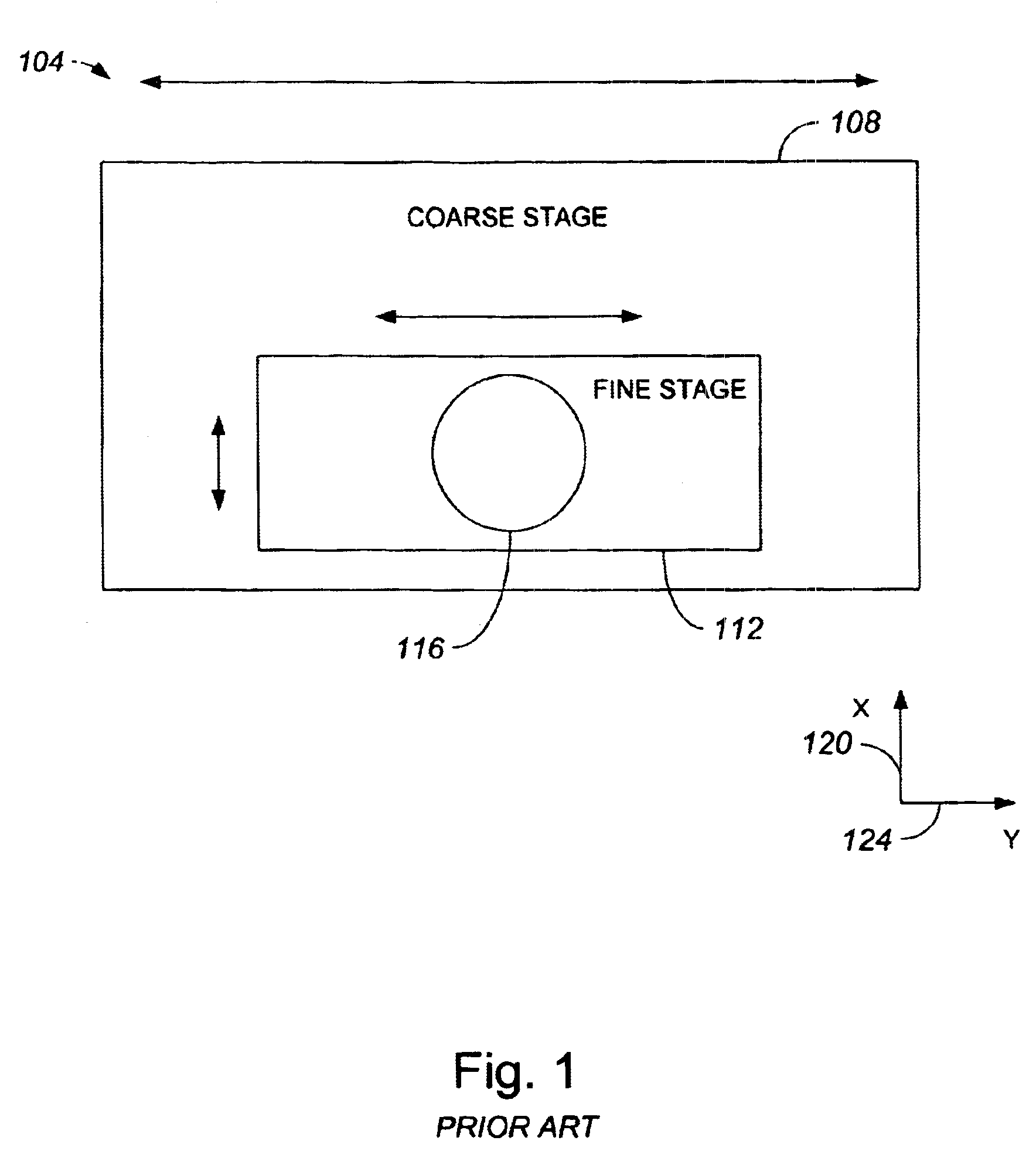
Increasing the acceleration capabilities of a reticle scanning stage generally results in an increase in the size of actuators used in the reticle scanning stage, as the increasing the efficiency and the power of an actuator often increases the size of the actuator.
While increasing the size of an actuator used to accelerate a coarse stage may be acceptable, increasing the size of an actuator that acts between the coarse stage and a fine stage often is not acceptable.
The mass associated with more efficient, more powerful actuators may adversely affect the performance of a fine stage, as the additional space needed by the more powerful actuators may not be readily available.
Further, actuators which have a relatively high efficiency rating and a relatively high power rating generally have lower positioning accuracy capabilities than actuators which have a lower efficiency rating and a lower power rating.
Conventionally, increasing the throughout requirements of a reticle scanning stage may cause the accuracy associated with the reticle scanning stage to be compromised, as actuators which are capable of higher accelerations are generally more difficult to control and, hence, less accurate.
In addition to being less accurate, it is also difficult to position large actuators such that a line of force associated with the actuators may cross through the center of gravity.
The use of such a balancing mass may further increase the size of the overall stage.

Method used


Image

  • Dual force mode fine stage apparatus
  • Dual force mode fine stage apparatus
  • Dual force mode fine stage apparatus

Examples


Embodiment Construction

[0038]Increasing the throughput requirements of a reticle scanning stage often requires that acceleration capabilities of the reticle scanning stage be increased, and causes the accuracy associated with the reticle scanning stage to be compromised. This compromise is due at least in part to the fact that actuators which are capable of higher accelerations are generally more difficult to control and, hence, less accurate. In addition to being less accurate, large actuators are also difficult to position such that a line of force associated with the actuators may cross through the center of gravity on the reticle scanning stage. When the line of force is not through the center of the center of gravity on the reticle scanning stage, then a fairly significant balancing mass which increases the overall size of the reticle scanning stage may be needed to balance the reticle scanning stage. In order to increase the accuracy associated with a reticle scanning stage and to substantially mini...


PUM

PropertyMeasurementUnit
wavelengthaaaaaaaaaa
speedaaaaaaaaaa
forceaaaaaaaaaa

Abstract

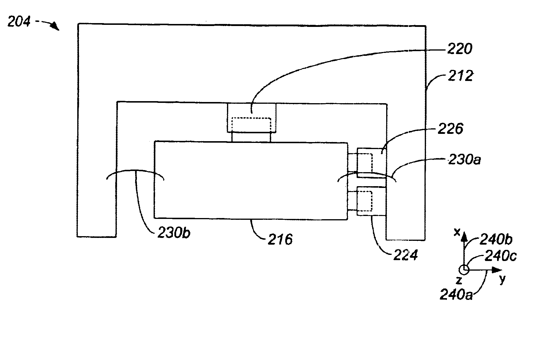
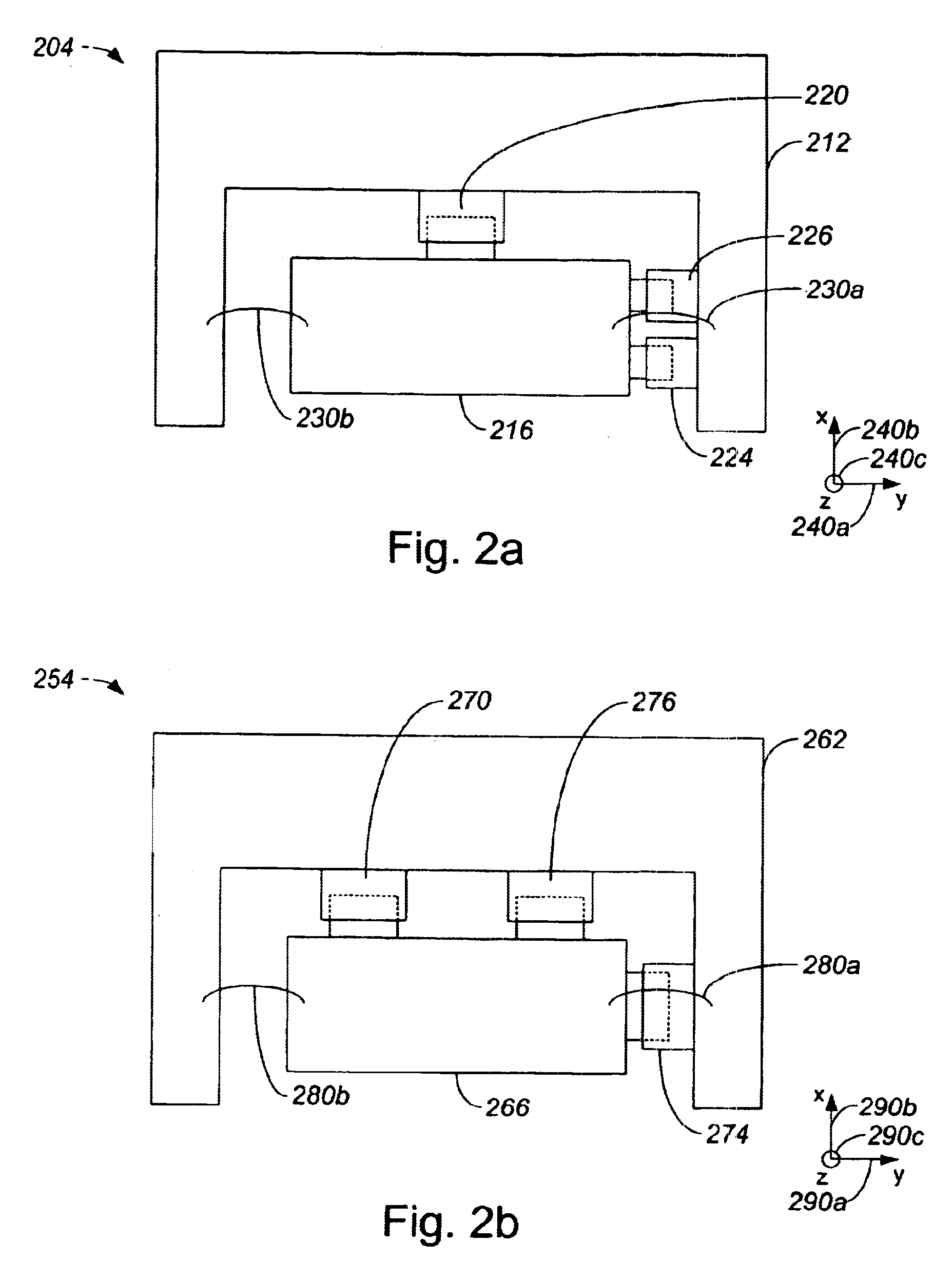
Methods and apparatus for both coarsely and accurately controlling a scanning stage are disclosed. According to one aspect of the present invention, an apparatus for scanning an object includes a first stage that is coupled to a first actuator which moves the first stage along an axis, as well as a second stage that is arranged to accommodate the object. A first coupler which has first and second ends is aligned along the axis such that the first and second ends of the first coupler contact the first and second stages, respectively. A second coupler which also has first and second ends is aligned along the axis such that the first and second ends of the second coupler contact the first and second stages, respectively. When the first stage scans in a first direction, the first coupler causes the second stage to scan along the axis through the first coupler.

Description

BACKGROUND OF THE INVENTION[0001]1. Field of Invention[0002]The present invention relates generally to semiconductor processing equipment. More particularly, the present invention relates to a scanning stage apparatus which provides for high acceleration when accuracy requirements are relatively low, and high accuracy when acceleration requirements are relatively low.[0003]2. Description of the Related Art[0004]Scanning stages such as reticle scanning stages are often used in semiconductor fabrication processes. Reticle scanning stages are generally used to accurately position a reticle or reticle for exposure over a semiconductor wafer. Patterns are generally resident on a reticle, which effectively serves as a mask or a negative for a wafer. In general, a reticle may be formed from a silicon nitride film on which a thin metal pattern is placed. When a reticle is positioned over a wafer as desired, a beam of light or a relatively broad beam of electrons may be collimated through a ...

Claims


Application Information

Patent Timeline
Patent Type & Authority Patents(United States)
IPC IPC(8): G03B27/42G03B27/62G03B27/58G03F7/20
CPCG03F7/70758G03F7/70716
Inventor POON, ALEX KA TIMCHERRY, III, ROYAL W.
Owner NIKON CORP
Learn More