Image processing apparatus, ink jet printing apparatus, and image processing method
- Summary
- Abstract
- Description
- Claims
- Application Information
AI Technical Summary
Benefits of technology
Problems solved by technology
Method used
Image
Examples
first embodiment
Fourth Variation of First Embodiment
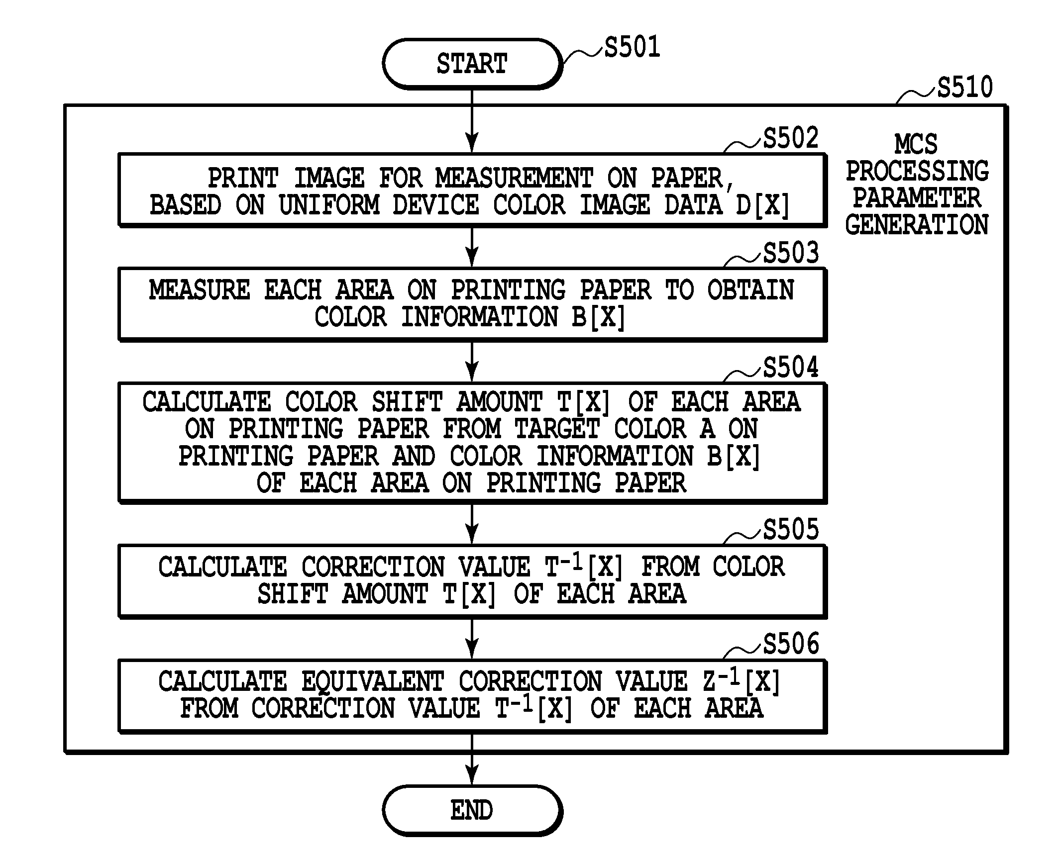
[0158]With respect to the number of printing characteristic ranks R[Y] described with reference to the first embodiment, as the number of printing characteristic ranks R[Y] increases, the number of table parameters for MCS processing previously stored in the memory increases. On the other hand, as the number of printing characteristic ranks R[Y] is reduced, the accuracy to correct the color shift is reduced. Therefore, in the present variation, although the number of printing characteristic ranks R[Y] are increased as much as possible, a representative rank N (M>N≧1) is set from printing characteristic ranks R[Y] for each of K, C, M, Y. Then, table parameters for the MCS processing are generated for only combinations of the representative ranks of each of K, C, M, Y; and with respect to printing characteristic ranks R[Y] other than the representative ranks, table parameters are generated by interpolation operation using the table parameters of the...
second embodiment
Third Variation of Second Embodiment
[0233]The present variation relates to a mode corresponding to the fourth variation of the first embodiment.
[0234]That is, a representative ranks N (M≧N≧2) for each K, C, M, Y is set from printing characteristic ranks R[Y], and representative table parameters for ink color conversion & MCS processing are generated in such a way that the representative table parameters correspond to combinations of the representative ranks of each of K, C, M, Y. Then, with respect to printing characteristic ranks R[Y] other than representative ranks, parameters for ink color conversion & MCS processing are generated by interpolation operation using representative parameters of ink color conversion & MCS processing.
Third Embodiment
[0235]FIG. 23A is a block diagram illustrating an example of an image processing configuration to generate print data according to a third embodiment of the present invention. The present embodiment is different from the configuration illu...
third embodiment
Second Variation of Third Embodiment
[0259]The present variation relates to a mode corresponding to the fourth variation of the first embodiment. That is, a representative rank N (M≧N≧2) for each K, C, M, Y is set from printing characteristic ranks R[Y], and representative table parameters for MCS processing are generated in such a way that they correspond to combinations of the representative ranks of each K, C, M, Y. Then, with respect to printing characteristic ranks R[Y] other than the representative ranks, parameters for MCS processing are generated by interpolation operation using the representative parameters for ink color conversion & MCS processing.
[0260]Application of methods described in the above first to third embodiments and variations thereof can reduce a color shift caused by printing characteristic variations among nozzles due to variations among nozzle ejection volumes in an image using two or more colors (secondary color image, tertiary color image). Also if an eje...
PUM
 Abstract
Description
Claims
Application Information
 - R&D
- Intellectual Property
- Life Sciences
- Materials
- Tech Scout
- Unparalleled Data Quality
- Higher Quality Content
- 60% Fewer Hallucinations
Browse by: Latest US Patents, China's latest patents, Technical Efficacy Thesaurus, Application Domain, Technology Topic, Popular Technical Reports.
© 2025 PatSnap. All rights reserved.Legal|Privacy policy|Modern Slavery Act Transparency Statement|Sitemap|About US| Contact US: help@patsnap.com


