Field Erectable Abatement System
a technology of abatement system and erectable platform, which is applied in the direction of separation process, industrial buildings, small buildings, etc., can solve the problems of insufficient field erectability, inability to efficiently field erect, and inability to transport current abatement system,
- Summary
- Abstract
- Description
- Claims
- Application Information
AI Technical Summary
Problems solved by technology
Method used
Image
Examples
first embodiment
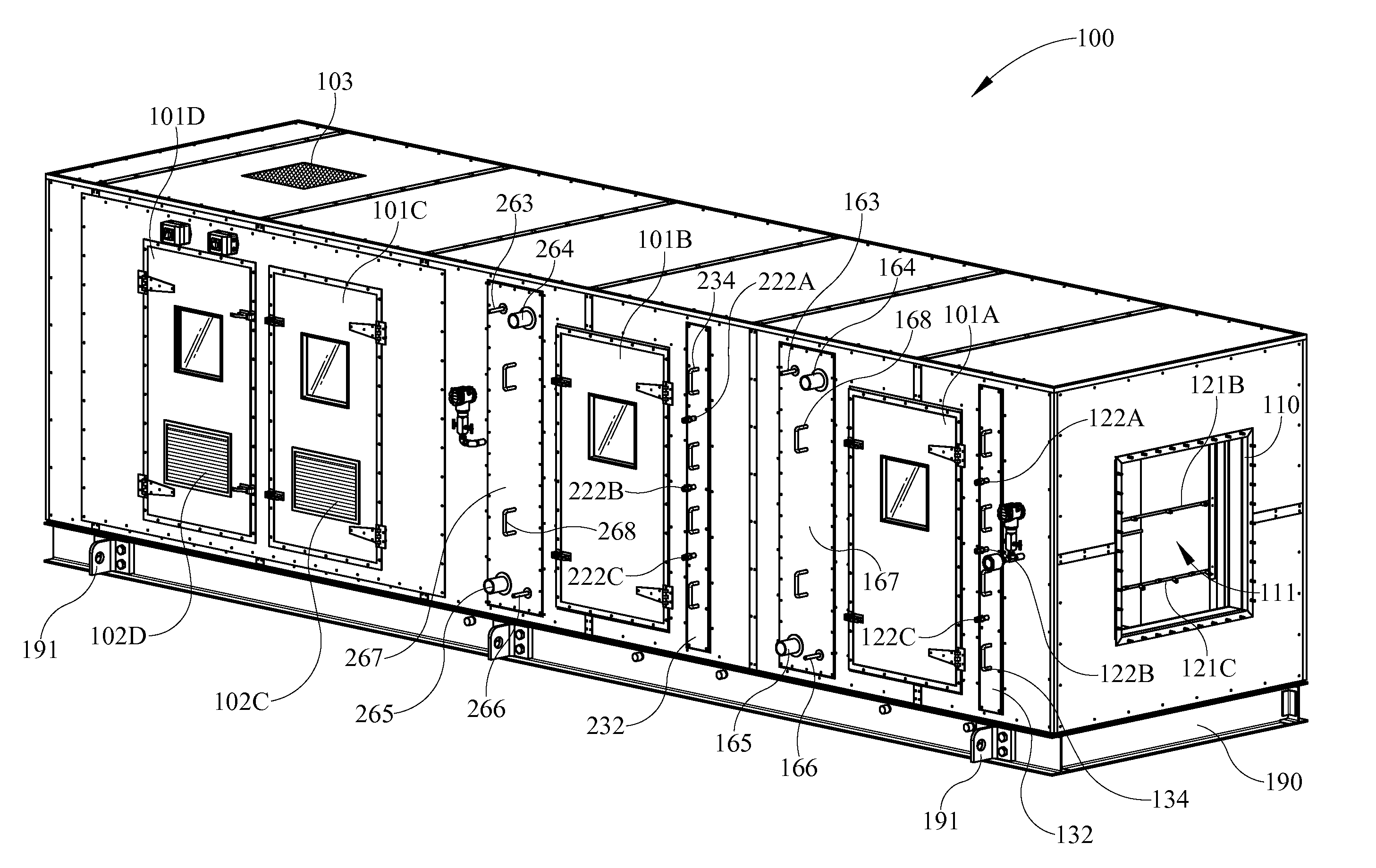
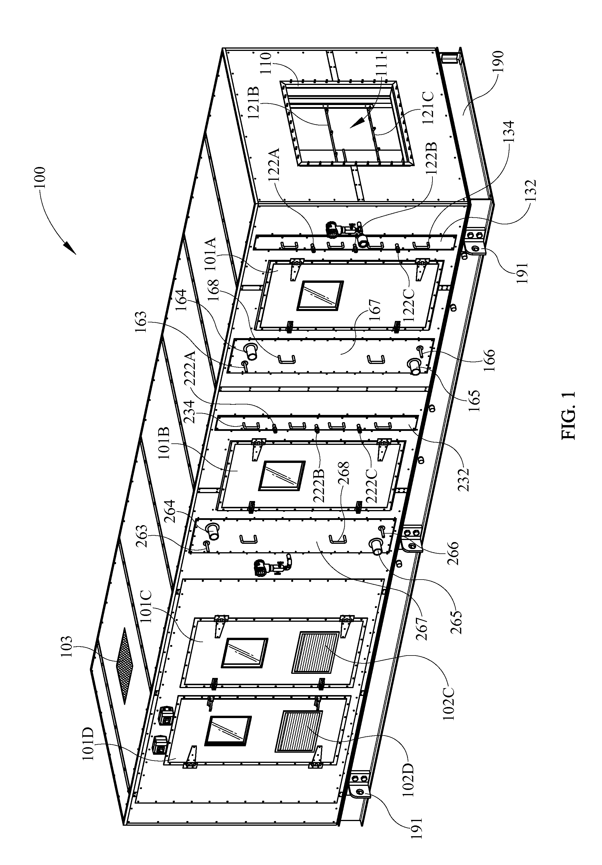
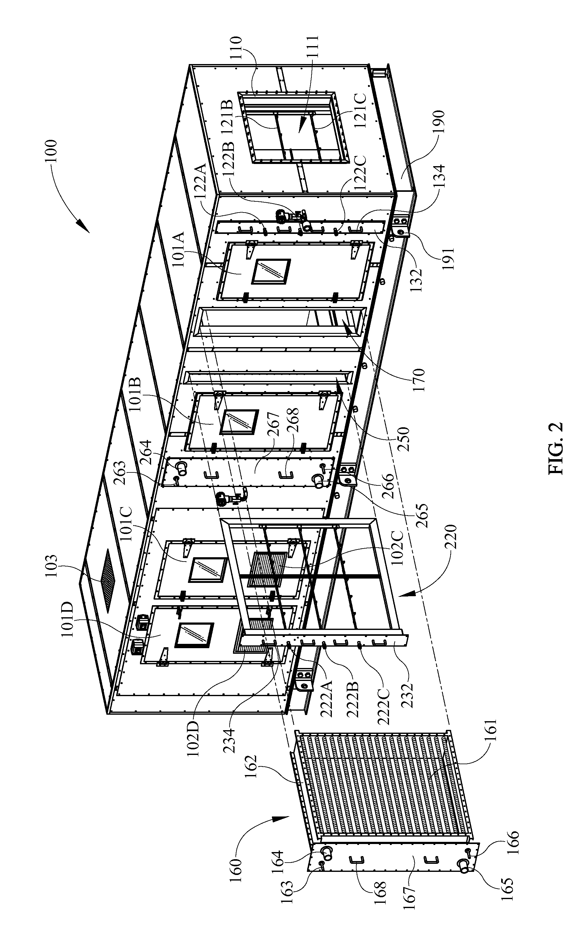
In FIG. 1 through FIG. 15 various aspects of an abatement system 100 are shown. Referring initially to FIG. 1 through FIG. 4, it is illustrated that the abatement system 100 includes a support base 190 supporting a structure having a generally longitudinally extending and generally rectangular shape. The support base 190 includes a plurality of lifting lugs 191 around the periphery thereof that may be utilized in lifting and placing the abatement system 100 in a desired installation spot. The lifting lugs 191 may optionally be removed once the abatement system 100 is placed in a desired location.
The abatement system 100 also includes an air inlet opening 110 that defines an air inlet 111. The air inlet 111 generally defines the beginning of an abatement chamber that extends interiorly through a portion of abatement system 100 and that will be described in additional detail herein. Air inlet 111 may be placed in communication with a polluted gas stream such as, for example, a flue ga...
second embodiment
Referring now to FIG. 16, a misting array 320 for use in an abatement system is illustrated. In some embodiments the misting array 320 may be utilized in an abatement system that removes pollutants from a flue gas created by the combustion of coal. The misting array 320 is similar to the first misting array 120 and the second misting array 220, but does not include a middle nozzle row. The misting array 320 includes a sealing piece 330 having a sealing plate 332 and a sealing plate extension 335. Two handles 334 are provided on an exterior face of the sealing plate 332. A frame structure is coupled to and extends from the sealing piece 330 and includes an upper frame structure member 341 having an upper frame structure rim portion (not shown), a side frame structure member 345 having a side frame structure rim portion 346, and a lower frame structure member 343 having a lower frame structure rim portion 344. The frame structure also includes a middle support bar 348 and a side suppo...
third embodiment
Referring now to FIG. 17, FIG. 18A, and FIG. 18B, aspects of a misting array 420 for use in an abatement system are depicted and described. FIG. 17 depicts portions of the sealing piece 430 of the misting array 420. The sealing piece 430 includes a sealing plate 432 having vertically aligned handles 434 thereon. Liquid source couplings 422A, 422B, and 422C of upper, middle, and lower nozzle tubings, respectively, are provided on an exterior side of sealing plate 432. Indicators 438A, 438B, and 438C are coupled to pipe nipples 423A, 423B, and 423C of upper, middle, and lower nozzle tubing proximal respective of liquid source couplings 422A, 422B, and 422C. Fiducial markings 439A, 439B, and 439C are provided on the sealing plate 432 proximal respective of the indicators 438A, 438B, and 438C. The positioning of the indicators 438A, 438B, and 438C with respect to the fiducial markings 439A, 439B, and 439C is indicative of the rotational orientation of respective nozzle tubing coupled to...
PUM
 Abstract
Description
Claims
Application Information
 - R&D
- Intellectual Property
- Life Sciences
- Materials
- Tech Scout
- Unparalleled Data Quality
- Higher Quality Content
- 60% Fewer Hallucinations
Browse by: Latest US Patents, China's latest patents, Technical Efficacy Thesaurus, Application Domain, Technology Topic, Popular Technical Reports.
© 2025 PatSnap. All rights reserved.Legal|Privacy policy|Modern Slavery Act Transparency Statement|Sitemap|About US| Contact US: help@patsnap.com


