Automatic and semi-automatic welding systems and methods

a semi-automatic welding and welding system technology, applied in the field of welding systems, can solve the problems of limiting the efficiency of welding in these contexts, and the difficulty of the welding operator to encounter difficulties

Active Publication Date: 2011-12-01
ILLINOIS TOOL WORKS INC
View PDF3 Cites 121 Cited by
  • Summary
  • Abstract
  • Description
  • Claims
  • Application Information

AI Technical Summary

Problems solved by technology

For example, in these applications, a welding operator may encounter difficulties when attempting to train a robotic welding device to react to non-uniformities in the weld joint.
In certain welding environments, such as shipbuilding, such factors continue to necessitate utilization of manual welding operators, thus limiting the efficiency of welding in these contexts.

Method used


Image

  • Automatic and semi-automatic welding systems and methods
  • Automatic and semi-automatic welding systems and methods
  • Automatic and semi-automatic welding systems and methods

Examples


Embodiment Construction

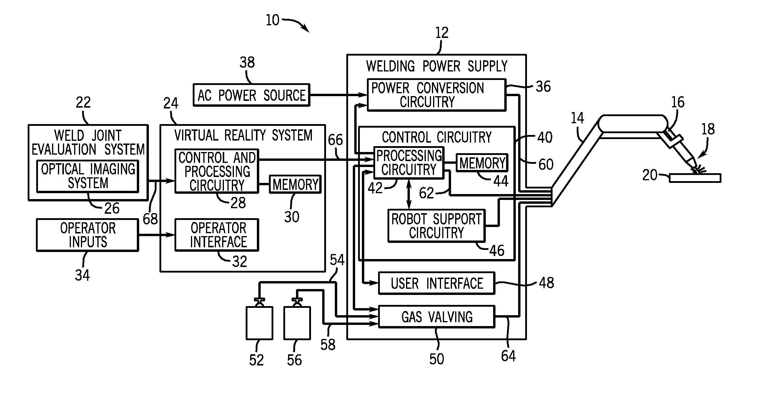
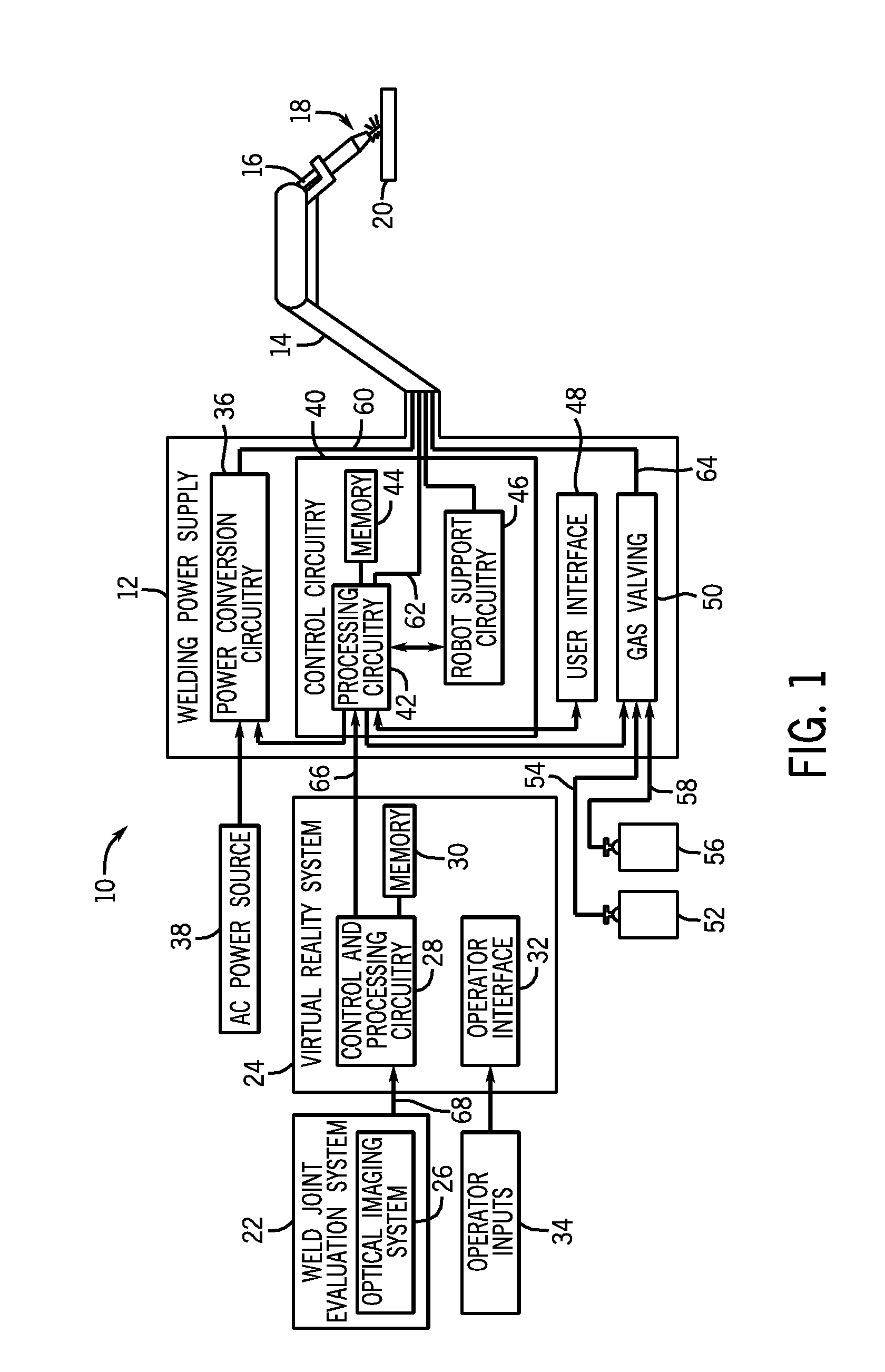
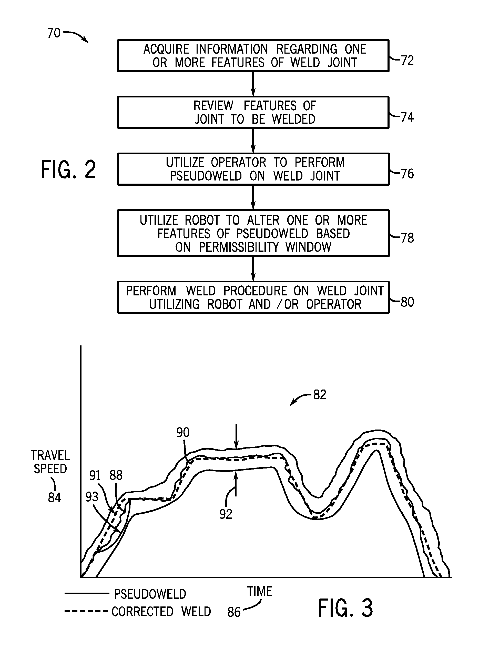
As described in detail below, systems and methods for controlling and performing a welding operation utilizing a robotic welding device and a welding operator are provided. Further, methods and systems for training a robotic welding device to properly perform a desired weld procedure are also disclosed. For example, in certain embodiments, a welding operator may generate a pseudoweld procedure for a given weld joint by utilizing a virtual reality system that is preloaded with information regarding the joint to be welded. For example, the virtual reality system may receive information regarding the weld joint from a suitable weld evaluation system, such as a laser scanning system. In these embodiments, a robotic welding device may be trained to weld the given weld joint based on the pseudoweld procedure and one or more known parameters of the given weld joint. That is, control circuitry for a robotic welding device may receive inputs, such as features of a weld joint (e.g., joint thi...


PUM

PropertyMeasurementUnit
thicknessaaaaaaaaaa
speedaaaaaaaaaa
voltageaaaaaaaaaa

Abstract

Methods and devices for control for an automated welding system are provided. Disclosed control methods may include receiving a data set including one or more features of a joint to be welded and receiving a weld procedure for the joint to be welded. The weld procedure for the joint is determined based on a sample virtual weld performed by an operator, a stored procedure developed for a substantially similar weld joint, or a combination thereof. The method may further include determining one or more desired changes to the weld procedure based on the received features of the joint to be welded and generating an updated weld procedure by altering one or more parameters of the received weld procedure in accordance with the one or more desired changes, wherein the one or more parameters are included within a predetermined allowable data set.

Description

BACKGROUNDThe invention relates generally to welding systems, and, more particularly, to automatic and semi-automatic welding systems and methods.Welding is a process that has become increasingly ubiquitous in various industries and applications. While many of these welding processes have been successfully automated, thus reducing the need for manual welding operators, a large number of applications continue to exist in which automation is not utilized due to factors such as the variability in the encountered weld joints, the need for adaptation while welding, and so forth. For example, in these applications, a welding operator may encounter difficulties when attempting to train a robotic welding device to react to non-uniformities in the weld joint. In certain welding environments, such as shipbuilding, such factors continue to necessitate utilization of manual welding operators, thus limiting the efficiency of welding in these contexts. Accordingly, there exists a need for improve...

Claims


Application Information

Patent Timeline
Patent Type & Authority Applications(United States)
IPC IPC(8): B23K11/00
CPCB23K9/00B23K9/0953G09B19/24B23K26/0884B23K9/32
Inventor ALBRECHT, BRUCE PATRICKBATZLER, TODD GERALDWALLER, MICHAEL LEO
Owner ILLINOIS TOOL WORKS INC
Why Eureka
Try Eureka