Sterilizing device and manufacturing method for sterilizing device

a technology of sterilizing device and manufacturing method, which is applied in the direction of instruments, wing knobs, therapy, etc., can solve the problems of light rays irradiating on objects

Inactive Publication Date: 2011-12-01
IND TECH RES INST
View PDF6 Cites 109 Cited by
  • Summary
  • Abstract
  • Description
  • Claims
  • Application Information

AI Technical Summary

Benefits of technology

[0016]The sterilizing device of the disclosure could be used in a variety of applications, for example, a publicly accessible apparatus having a manual activation device. According to one embodiment, the sterilizing device could be implemented as a touch panel, a door handle, an automatic door switch, and a touch mobile phone. During operation, when a user physically touches the front surface of the light guiding member of the sterilizing device, an evanescent wave goes out of the front surface and then propagates along the surface of the light guiding member. Therefore the contact area of the user will be disinfected by UV light rays. The sterilizing device could also sterilize the surface, if there are pathogens adhere to the surface, the evanescent UV light rays will irradiate on them and kill the pathogens on the surface.

Problems solved by technology

When an object contacts or comes close to the surface, the UV light rays irradiate on the object due to a frustrated total internal reflection phenomenon.

Method used


Image

  • Sterilizing device and manufacturing method for sterilizing device
  • Sterilizing device and manufacturing method for sterilizing device
  • Sterilizing device and manufacturing method for sterilizing device

Examples


Embodiment Construction

[0037]Exemplary embodiments will now be described more fully with reference to the accompanying drawings. The embodiments may, however, be embodied in many different forms and should not be construed as limited to the embodiments set forth herein. Rather, these embodiments are provided so that this disclosure will be thorough and complete, and will fully convey the scope of the embodiments to those skilled in the art.

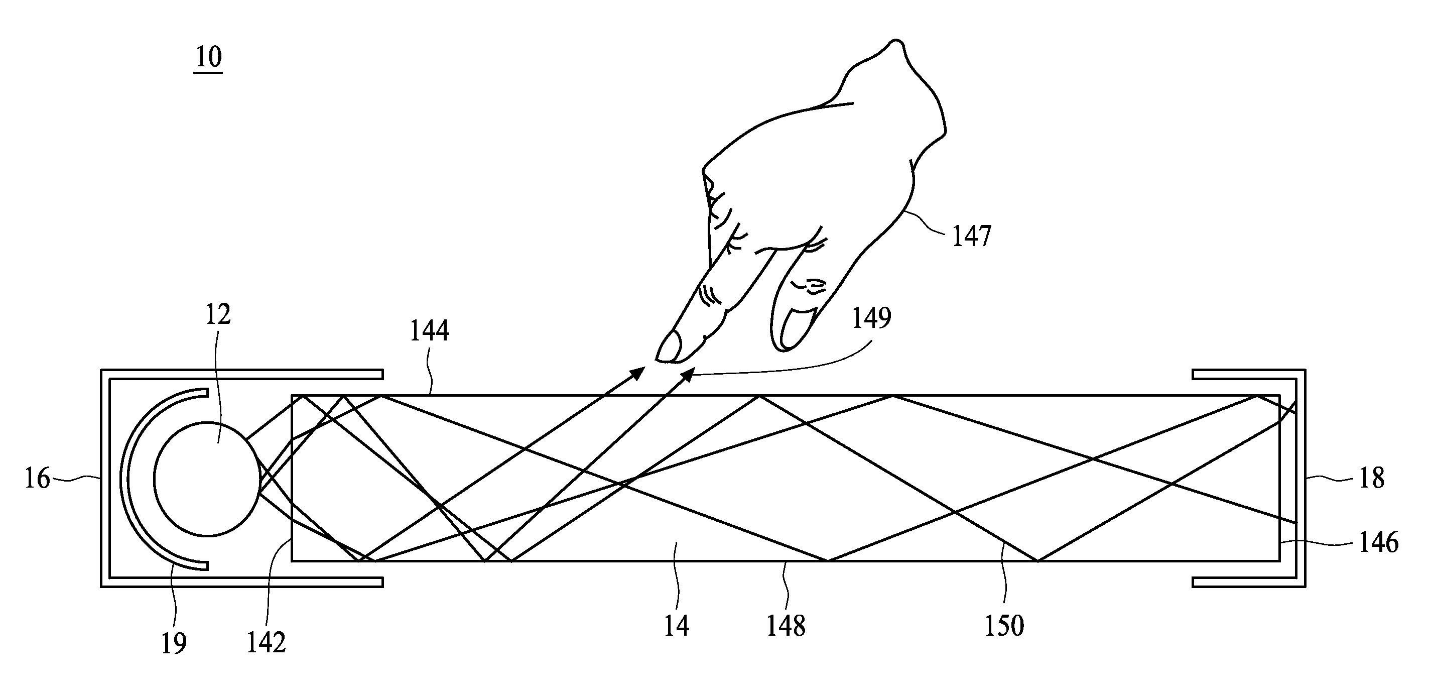
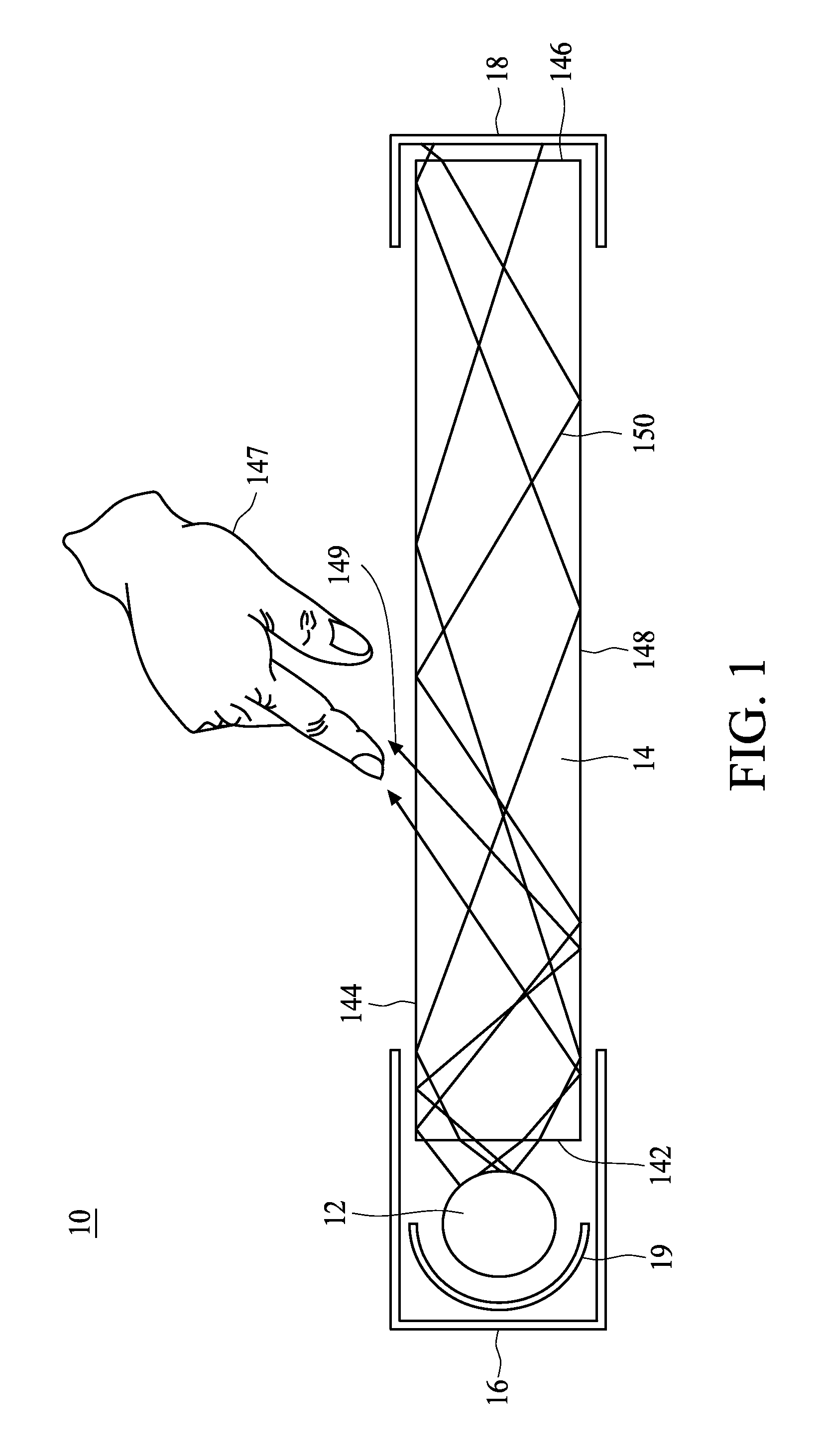
[0038]FIG. 1 shows a cross-sectional view of a sterilizing device 10 in accordance with an exemplary embodiment. The sterilizing device 10 comprises a short wavelength light source 12 and a slab of dielectric material as a light guiding member 14. In this embodiment, the light source 12 is an ultraviolet (UV) light source configured to generate ultraviolet light rays (a ray is an idealized narrow beam of light) or an ultraviolet light beam for sterilization. Generally, UV light rays are classified into four types: UV-A light rays having wavelength from 320 nm to 400 nm,...


PUM

PropertyMeasurementUnit
wavelengthaaaaaaaaaa

Abstract

A sterilizing device comprises a light guiding member and an ultraviolet (UV) light source. The light guiding member has a surface. The UV light source emits UV light rays such that the UV light rays are guided into the guiding member based on a total internal reflection. When an object contacts or comes close to the surface, an evanescent wave from the UV light rays irradiates on the object.

Description

CROSS-REFERENCE TO RELATED APPLICATIONS[0001]This application is an application under 35 USC 111(a) and claims priority under 35 USC 119 from Provisional Application Ser. No. 61 / 347,933, filed May 25, 2010 under 35 USC 111(b), the disclosure of which is incorporated herein by reference.STATEMENT REGARDING FEDERALLY SPONSORED RESEARCH OR DEVELOPMENT[0002]Not applicable.NAMES OF THE PARTIES TO A JOINT RESEARCH AGREEMENT[0003]Not applicable.INCORPORATION-BY-REFERENCE OF MATERIALS SUBMITTED ON A COMPACT DISC[0004]Not applicable.BACKGROUND OF THE INVENTION[0005]1. Field of the Invention[0006]The present disclosure relates to a sterilizing device and a manufacturing method for a sterilizing device.[0007]2. Description of Related Art Including Information Disclosed Under 37 CFR 1.97 and 37 CFR 1.98.[0008]Virus and bacteria are easily introduced into a human body through the subject's hands when the subject operates public facilities by physically touching a surface of a touch activation de...

Claims


Application Information

Patent Timeline
Patent Type & Authority Applications(United States)
IPC IPC(8): G06F3/042H05K13/00A61L2/10
CPCA61L2/10Y10T29/49002A61N5/0624E05B1/0069
Inventor SHR, REN CHINWU, TENG CHUNLIANG, WEI YUNKUO, CHIH WEI
Owner IND TECH RES INST
Why Eureka
Try Eureka