
Articles which include chevron film cooling holes, and related processes

a technology of cooling holes and chevron films, applied in the direction of liquid fuel engines, vessel construction, marine propulsion, etc., can solve problems such as engine efficiency suffer

Active Publication Date: 2011-12-01
GENERAL ELECTRIC CO
View PDF8 Cites 362 Cited by
  • Summary
  • Abstract
  • Description
  • Claims
  • Application Information

AI Technical Summary

Problems solved by technology

The need for cooling systems in gas turbine engines is critical, since the engines usually operate in extremely hot environments.
Moreover, since a large number of film cooling holes require a larger amount of air to be bled off the engine compressor, engine efficiency may suffer if too many cooling holes are present.

Method used


Image

  • Articles which include chevron film cooling holes, and related processes
  • Articles which include chevron film cooling holes, and related processes
  • Articles which include chevron film cooling holes, and related processes

Examples


example

[0083]The examples presented below are intended to be merely illustrative, and should not be construed to be any sort of limitation on the scope of the claimed invention.

[0084]Modeling studies were carried out on film cooling effectiveness, as a function of the (X / Ms) value, for a number of different, modeled shapes. (The non-dimensional distance “X / Ms” is the ratio of the axial distance “x” along the cooled surface, starting at the film hole exit, to the product of M*s, where “M” is the blowing ratio, and “s” is the equivalent two-dimensional slot height representing the same flow area as the film hole bore cross-section). In one instance, a standard diffuser-type passage hole was evaluated, i.e., a passage hole with no chevron characteristics at the hole exit, instead terminating in a standard, trapezoidal shape. Chevron-shaped holes which generally conform to the chevron geometry specified in U.S. Pat. No. 7,328,580 (Lee et al, discussed previously) were also evaluated, along wit...


PUM

PropertyMeasurementUnit
Fractionaaaaaaaaaa
Fractionaaaaaaaaaa
Fractionaaaaaaaaaa

Abstract

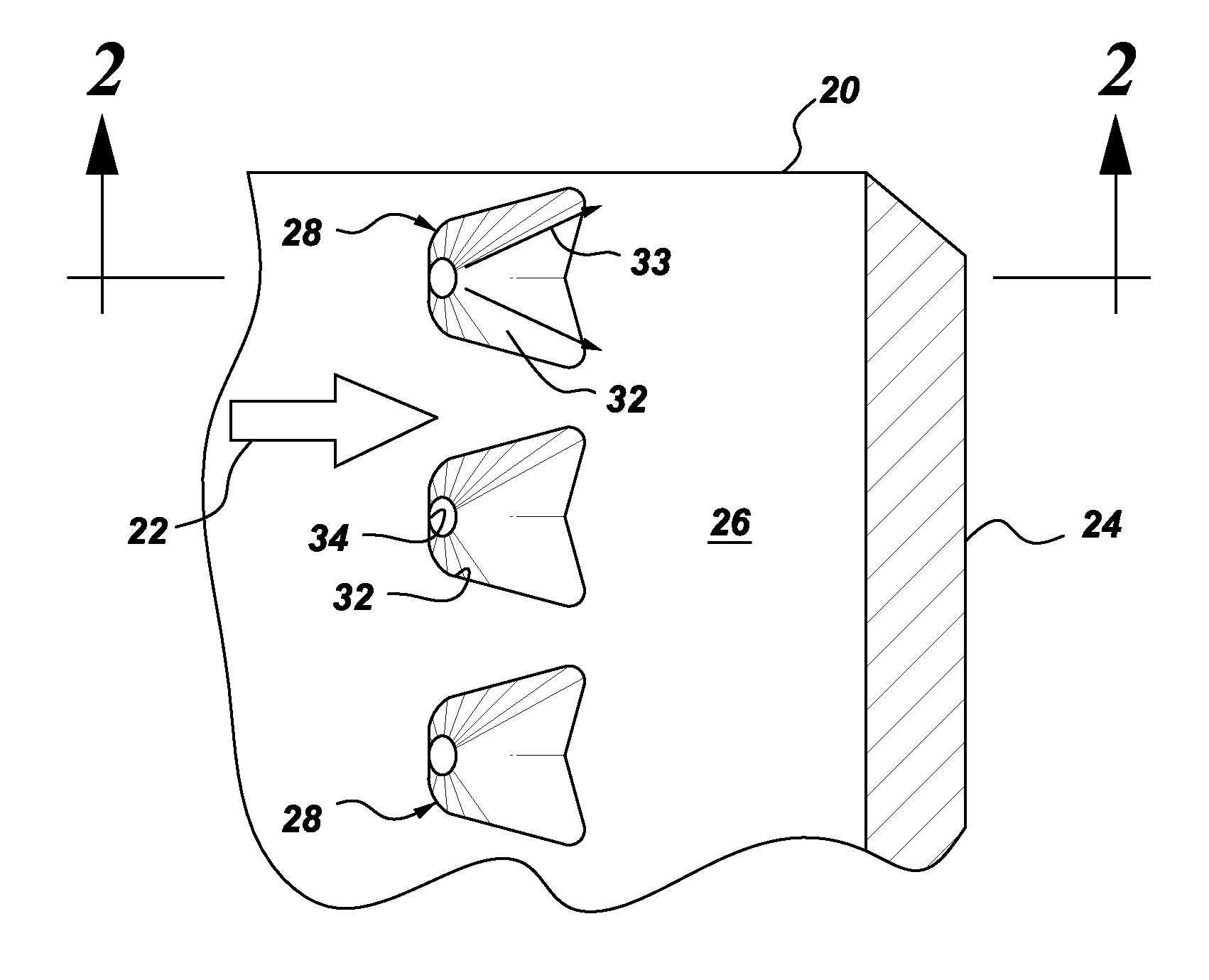
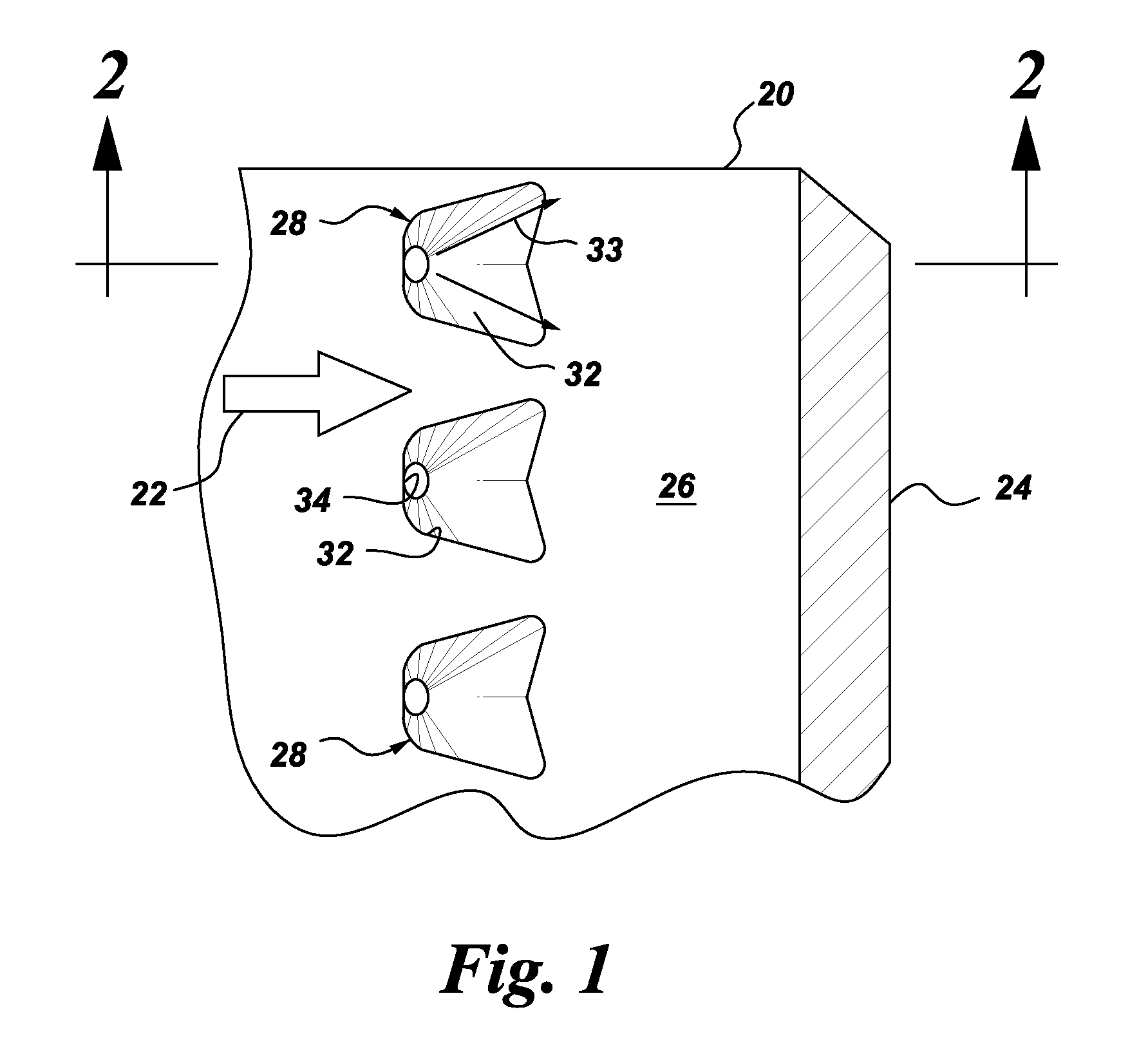
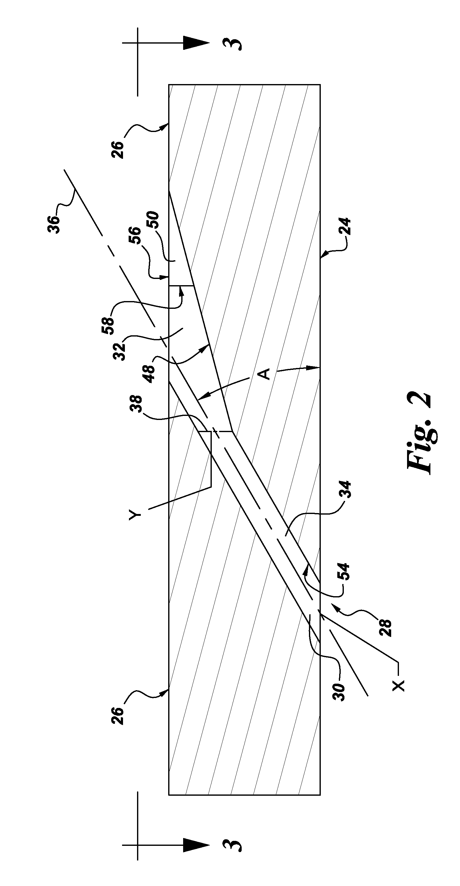
An article is described, including an inner surface which can be exposed to a first fluid; an inlet; and an outer surface spaced from the inner surface, which can be exposed to a hotter second fluid. The article further includes at least one row or other pattern of passage holes. Each passage hole includes an inlet bore extending through the substrate from the inlet at the inner surface to a passage hole-exit proximate to the outer surface, with the inlet bore terminating in a chevron outlet adjacent the hole-exit. The chevron outlet includes a pair of wing troughs having a common surface region between them. The common surface region includes a valley which is adjacent the hole-exit; and a plateau adjacent the valley. The article can be an airfoil. Related methods for preparing the passage holes are also described.

Description

STATEMENT REGARDING FEDERALLY SPONSORED RESEARCH & DEVELOPMENT[0001]This invention was made with Government support under contract number DE-FC26-05NT42643, awarded by the Department of Energy. The Government has certain rights in the invention.BACKGROUND[0002]The general subject matter of this invention relates to gas turbine engines, and, more specifically, to structures for cooling various components of the engines.[0003]A gas turbine engine includes a compressor, in which engine air is pressurized. The engine also includes a combustor, in which the pressurized air is mixed with fuel, to generate hot combustion gases. In a typical design (e.g., for aircraft engines or stationary power systems), energy is extracted from the gases in a high pressure turbine (HPT) which powers the compressor, and in a low pressure turbine (LPT). The low pressure turbine powers a fan in a turbofan aircraft engine application, or powers an external shaft for marine and industrial applications.[0004]Th...

Claims


Application Information

Patent Timeline
IPC IPC(8): F01D5/18B21D53/78B23K26/382
CPCF01D5/186Y02T50/67Y10T29/49316Y02T50/676F05D2230/10Y02T50/672Y02T50/60
Inventor BUNKER, RONALD SCOTTLACY, BENJAMIN PAUL
Owner GENERAL ELECTRIC CO
Learn More