Antenna amplifier device and antenna device provided in mobile object

an amplifier device and antenna technology, applied in amplifiers, amplifiers with semiconductor devices/discharge tubes, amplifiers, etc., can solve the problems of increased noise voltage, increased noise level, and insufficient noise factor of amplifier circuits, so as to reduce the number of components, reduce cost, and improve performance

Inactive Publication Date: 2011-12-01
FUJITSU GENERAL LTD
View PDF5 Cites 7 Cited by
  • Summary
  • Abstract
  • Description
  • Claims
  • Application Information

AI Technical Summary

Benefits of technology

[0020]The high frequency control unit for controlling the NF matching circuit provided in the antenna amplifier device can perform integral control on the basis of the channel select information for each of the antenna amplifier devices transmitted from the head unit via the data transmission line. Therefore, the antenna device can achieve high performance while reducing co...

Problems solved by technology

Although a high gain can be obtained with use of any of the above conventional impedance matching circuits, an amplification circuit does not necessarily provide a good noise factor (NF).
Although a signal level can be improved by increasing the signal source impedance with use of the step-up coil or the like, a noise voltage also incr...

Method used


Image

  • Antenna amplifier device and antenna device provided in mobile object
  • Antenna amplifier device and antenna device provided in mobile object
  • Antenna amplifier device and antenna device provided in mobile object

Examples


Embodiment Construction

[0038]An antenna amplifier device according to the present invention and an antenna device into which the antenna amplifier device is incorporated will be hereinafter explained.

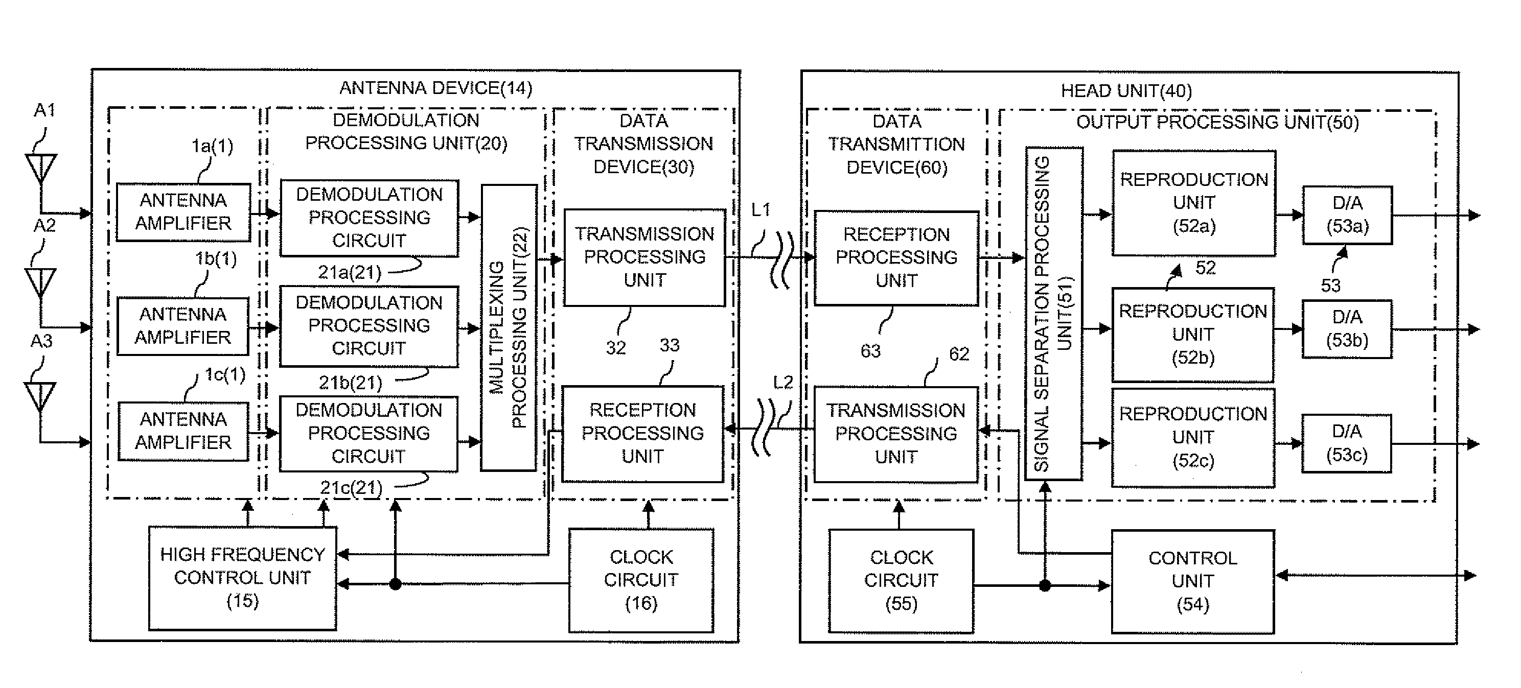
[0039]As shown in FIGS. 7A, 7B, a plurality of antennas A for receiving broadcast waves of different signal systems, such as an AM broadcasting reception antenna, an FM broadcasting reception antenna, and a digital TV reception antenna, are provided on a rear window of an automobile serving as a mobile object. An antenna device 14 is provided near to the respective antennas. In FIGS. 7A, 7B, the antennas A for three systems are shown simply such that they are provided in one region. However, the antennas A for the three systems may be provided in different regions.

[0040]A controller 60 of an audio apparatus is provided in front of the left of a driver's seat. A head unit 40 serving as an integrated reception apparatus is provided near to the controller 60. The antenna device 14 and the head unit 40 are connec...


PUM


Abstract

Even when an input is weak, an antenna amplifier device may achieve a high sensitivity while reducing a noise factor (NF). The antenna amplifier device includes an amplification circuit 7 for amplifying a high frequency signal received by an antenna A, and an NF matching circuit 5 provided between the amplification circuit 7 and the antenna A of which input impedance has a capacitance, the NF matching circuit 5 for switching the input impedance to the amplification circuit7 in accordance with a reception frequency. The NF matching circuit 5 includes a plurality of coils having different inductances, and at least one switch SW for connecting one of the coils, selected in accordance with the reception frequency, between the antenna A and the amplification circuit 7. A step-up coil SC is interposed between the NF matching circuit 5 and the amplification circuit 7.

Description

[0001]This application is based on an application No. 2010-120678 filed in Japan, the contents of which are hereby incorporated by reference.BACKGROUND OF THE INVENTION[0002]1. Field of the Invention[0003]The present invention relates to an antenna amplifier device and an antenna device.[0004]2. Description of the Related Art[0005]In a reception system provided in a mobile object for receiving broadcast waves such as AM broadcasting, FM broadcasting, and digital television broadcasting, an antenna amplifier device is used to reduce transmission loss by matching impedances between an antenna and an audio apparatus and to prevent reduction of an S / N ratio.[0006]Japanese Unexamined Patent Publication No. H10-209897 discloses a tunable antenna device having an antenna element of ¼ wavelength with respect to a reception frequency and always obtaining an optimum VSWR according to the reception frequency of a receiver. The tunable antenna device has an LC series resonance circuit interpose...

Claims


Application Information

Patent Timeline
IPC IPC(8): H04B1/18H03F1/56
CPCH03F1/26H03F1/565H03F3/195H04B1/18H03F2200/222H03F2200/451H03F2200/165
Inventor KAWAI, KENJITAKAYAMA, KAZUO
Owner FUJITSU GENERAL LTD
Why Eureka
Try Eureka