Hinge assembly

a technology of hinges and parts, applied in the direction of hinges, machine supports, manufacturing tools, etc., can solve the problems of many limitations and deficiencies of known devices, and achieve the effect of easy service and large load

Active Publication Date: 2011-12-08
WOOD WESLEY +1
View PDF13 Cites 25 Cited by
  • Summary
  • Abstract
  • Description
  • Claims
  • Application Information

AI Technical Summary

Benefits of technology

[0011]The hinge also can include: a flexible conduit, braided conduit, or flexible cable tray assembly disposed within the housing, wherein an open motion to the hinge extends the flexible conduit assembly from the housing, and wherein a close motion to the hinge retracts the flexible conduit assembly into the housing; and an end cap disposed upon a distal end of the flexible conduit assembly to prevent overextension. A seating spring is utilized to provide a tension and retract the conduit to a nested position. Additionally, the seating spring provides structural security and safety by preventing the overextension, and potential crush of the flexible conduit if left overextended when a doors closes.
[0017]The hinge assembly further can include: a flexible conduit, braided conduit, or flexible cable tray assembly disposed within the housing, wherein an open motion to the hinge extends the flexible conduit assembly from the housing, and wherein a close motion to the hinge retracts the flexible conduit assembly into the housing; and an end cap disposed upon a distal end of the flexible conduit assembly to prevent overextension. A seating spring is utilized to provide a tension and retract the conduit to a nested position. Additionally, the seating spring provides structural security and safety by preventing the overextension, and potential crush of the flexible conduit if left overextended when a doors closes.
[0020]Advantageously, the hinge disclosed herein can accommodate CAT-5, and other large gauge wires, and multiple wires, and other mediums of exchange. Also advantageously, the installation and use of the hinge disclosed herein does not require extensive coordination between a client, distributor, and vendor. Further advantageously, the hinge disclosed herein is easily serviced and can bear large loads while providing a means of power transfer.

Problems solved by technology

There are many limitations and deficiencies with these known devices.

Method used


Image

  • Hinge assembly
  • Hinge assembly
  • Hinge assembly

Examples


Embodiment Construction

[0065]Before describing the disclosed embodiments of this technology in detail, it is to be understood that the technology is not limited in its application to the details of the particular arrangement shown here since the technology described is capable of other embodiments. Also, the terminology used herein is for the purpose of description and not of limitation.

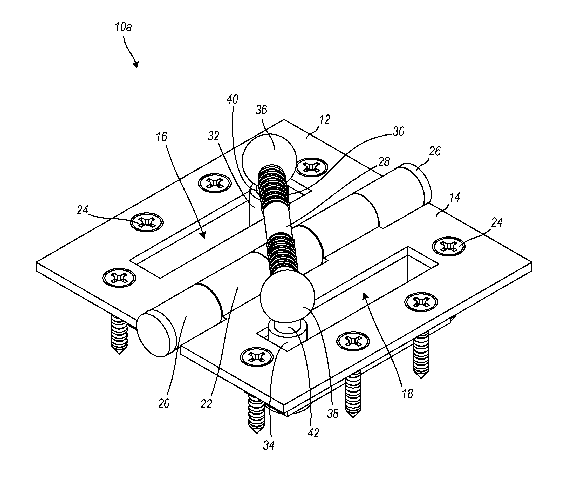
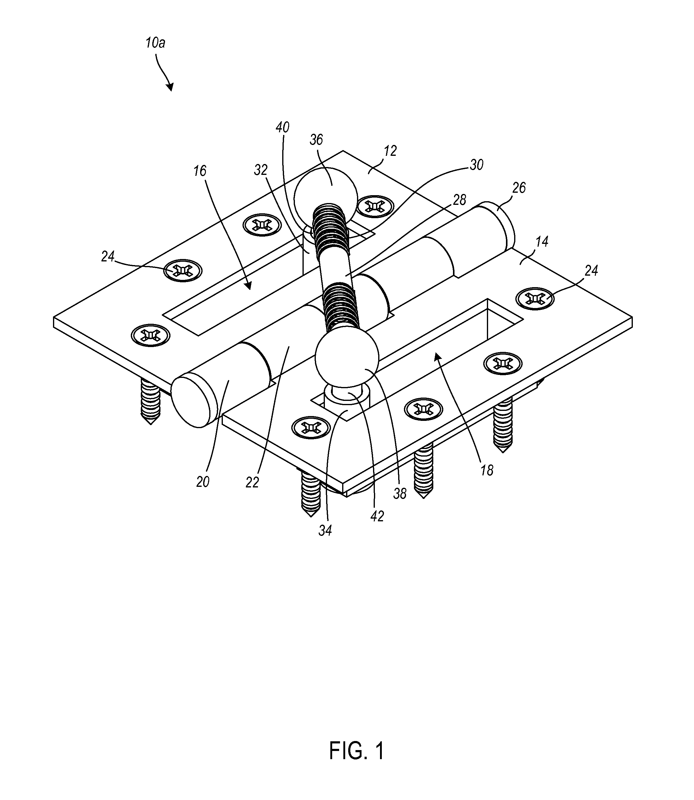
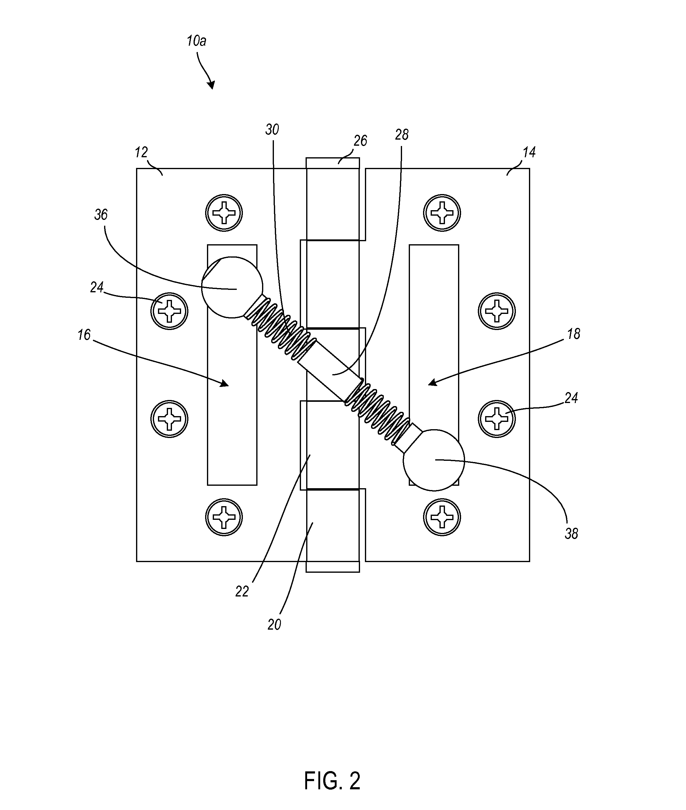
[0066]In various exemplary embodiments, the technology described herein provides a device, system, and associated methods for a hinge, hinge assembly, and door assembly. In each embodiment a hinge is configured to receive a conduit adapted to receive and pass through a medium of power transfer. Power transfer is accommodated in various embodiments, for electrical, optical, pneumatic, hydraulic, and the like, power transfer mediums. Additionally, in various embodiments, the hinge assembly includes an embedded switch. It at least one embodiment, the hinge embedded switch carries only power. In at least one alternative embodi...


PUM


Abstract

A hinge is provided. In at least one embodiment, the hinge includes: a first hinge leaf; a second hinge leaf interleaved with the first hinge leaf; a housing defined within a posterior side of at least one of the first hinge leaf and the second hinge leaf and configured to receive a conduit adapted to receive and pass through a medium of power transfer from the first hinge leaf to the second hinge leaf on an anterior side of the first hinge leaf and second hinge leaf; and an aperture defined on the anterior side of at least one of the first hinge leaf and the second hinge leaf through which to access the housing. In various embodiments the hinge can include multiple housings, fittings, turrets, and ball-and-socket fittings. In various embodiments, conduits are flexible, rigid, both flexible and rigid, elastic, braided, and telescoping.

Description

FIELD OF THE INVENTION[0001]The technology described herein relates generally to hinges and door wire routing systems. More specifically, this technology relates to a hinge assembly with which to hang a door and through which to route a wire, or the like, in a concealed, protected manner.BACKGROUND OF THE INVENTION[0002]Door hinges, door routing systems, power transfer hinges, and electrical hinges are known in the art. By way of example, known devices can include passing wires through or around a hinge pin within one or more hinge knuckles, utilizing a space created within a common bore created by interleaved knuckles, utilizing recesses in hinge leaves, utilizing passageways bored in hinge leaves, and utilizing routing systems that are not themselves hinges and from which a door cannot be hung. There are many limitations and deficiencies with these known devices.[0003]Related patents and published patent applications known in the art include the following: U.S. Pat. No. 4,412,711,...

Claims


Application Information

Patent Timeline
Patent Type & Authority Applications(United States)
IPC IPC(8): E05D11/00F16L3/08E06B7/28E05D5/02
CPCE05D5/04E05D11/0081E06B7/28Y10T16/522Y10T16/558Y10T16/551Y10T16/625F16L3/015
Inventor WOOD, WESLEYWOOD, MATTHEW
Owner WOOD WESLEY
Why Eureka
Try Eureka