Outside rear view mirror for vehicles, preferably for motor vehicles

a technology for rearview mirrors and vehicles, which is applied in the direction of mirrors, instruments, mountings, etc., can solve the problems of relative heavyness and cost-intensive manufacturing, and achieve the effects of reducing friction, reducing friction, and facilitating sliding coating

Inactive Publication Date: 2010-06-29
SMR PATENTS S A R L
View PDF21 Cites 7 Cited by
  • Summary
  • Abstract
  • Description
  • Claims
  • Application Information

AI Technical Summary

Benefits of technology

[0009]The U-shaped shoulder reduces friction between the parking lock and the support of the mirror head in that, in the plastic components (support, parking lock) of the U-shaped shoulder that come in contact when under load, the plastic components only touch linearly at two sites. To further reduce friction the U-shaped shoulder can be provided with an easily sliding coating. The U-shaped shoulder also has the task of transferring the force acting between the parking lock and the support and distributing it to the hinge axes. By this distribution of forces to several components and sections, damage or failure after frequent pivoting is reliably avoided.
[0010]Another variant represents the use of an additional securing element advantageously designed as a retaining clip to prevent overextension of the mirror head during a pivot movement forward in the direction of travel. In this case an additional, for example, U-shaped retaining clip is incorporated in the rear hinge receptacle to pivot together with the retaining clip acting as intermediate articulation. With its other end this additional retaining clip slides in an elongated hole of the support and because of its sliding possibility along the elongated hole it limits the pivot movement of the mirror head in the direction of travel. This additional retaining clip can be arranged in the internal region of the retaining clip forming the intermediate articulation.
[0011]Both retaining clips are simple bending parts made from a preferably non-corroding metal and can be produced simply and very cost effectively. The low weight and favorable distribution of the acting forces permits simple and less strongly dimensioned designs of the reinforcements and / or support sites in the mirror head and in the mirror foot.

Problems solved by technology

They require an installation space corresponding to their dimensions and are relatively heavy and cost-intensive to manufacture because of the metal design.

Method used


Image

  • Outside rear view mirror for vehicles, preferably for motor vehicles
  • Outside rear view mirror for vehicles, preferably for motor vehicles
  • Outside rear view mirror for vehicles, preferably for motor vehicles

Examples


Embodiment Construction

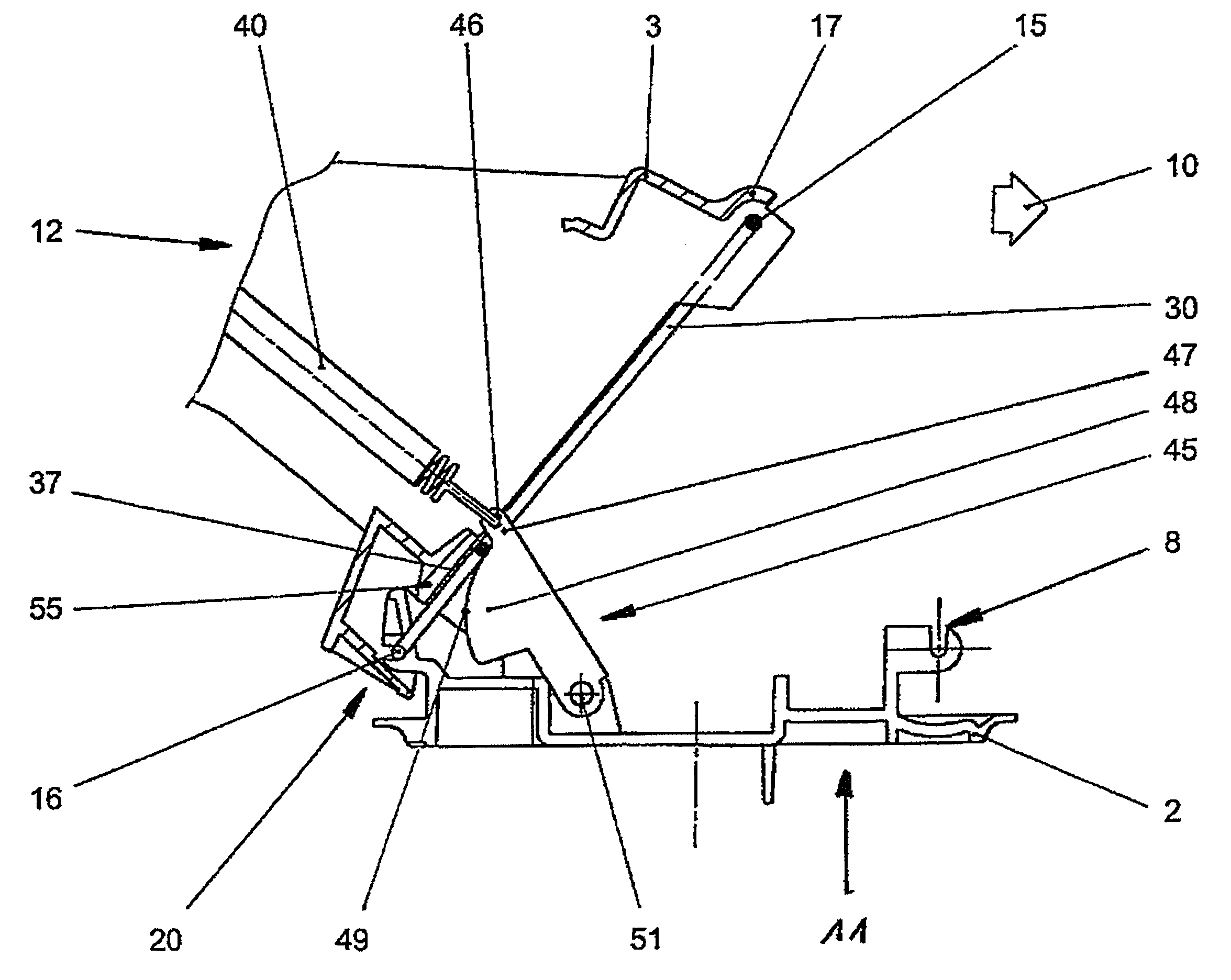
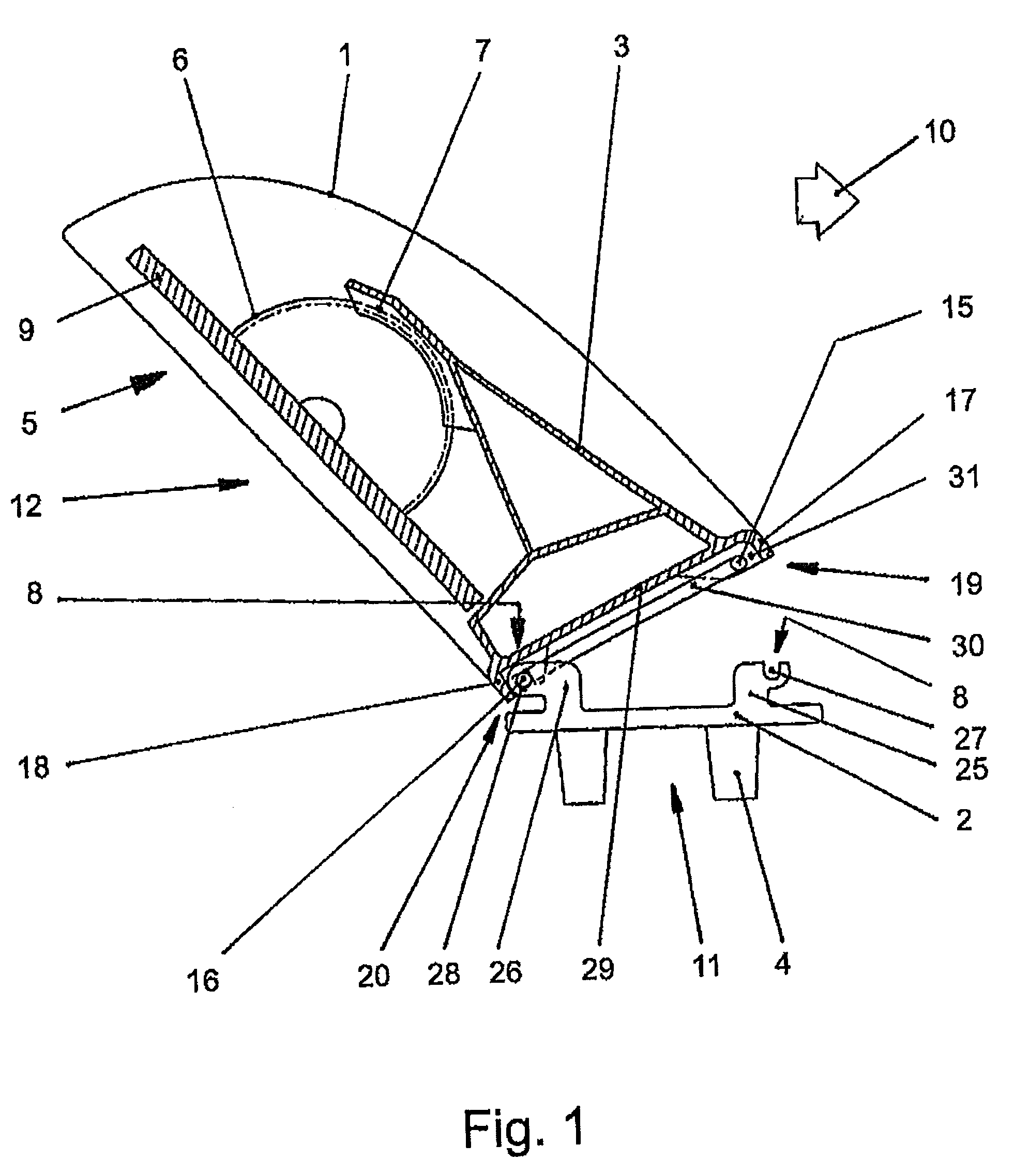
[0025]A cross section through an outside rear view mirror 5 in the state tilted opposite the travel direction 10 is shown in FIG. 1. The outside rear view mirror 5 consists essentially of the mirror head 12 and a mirror foot 11, which is fastened in known fashion to a vehicle. The mirror head 12 is mounted to be tilted forward or rearward on mirror foot 11 in the direction of travel 10.

[0026]The mirror head 12 has a housing 1 in which a mirror support 9 is arranged. It can be pivoted via an adjustment drive 6 and a gear mechanism 7 in the horizontal and / or vertical direction. The adjustment drive 6 is fastened in the rear area of the mirror 5 by common fastening devices, like screws, clips, etc. The gear mechanism 7 is firmly connected to a support 3 of the mirror head 12.

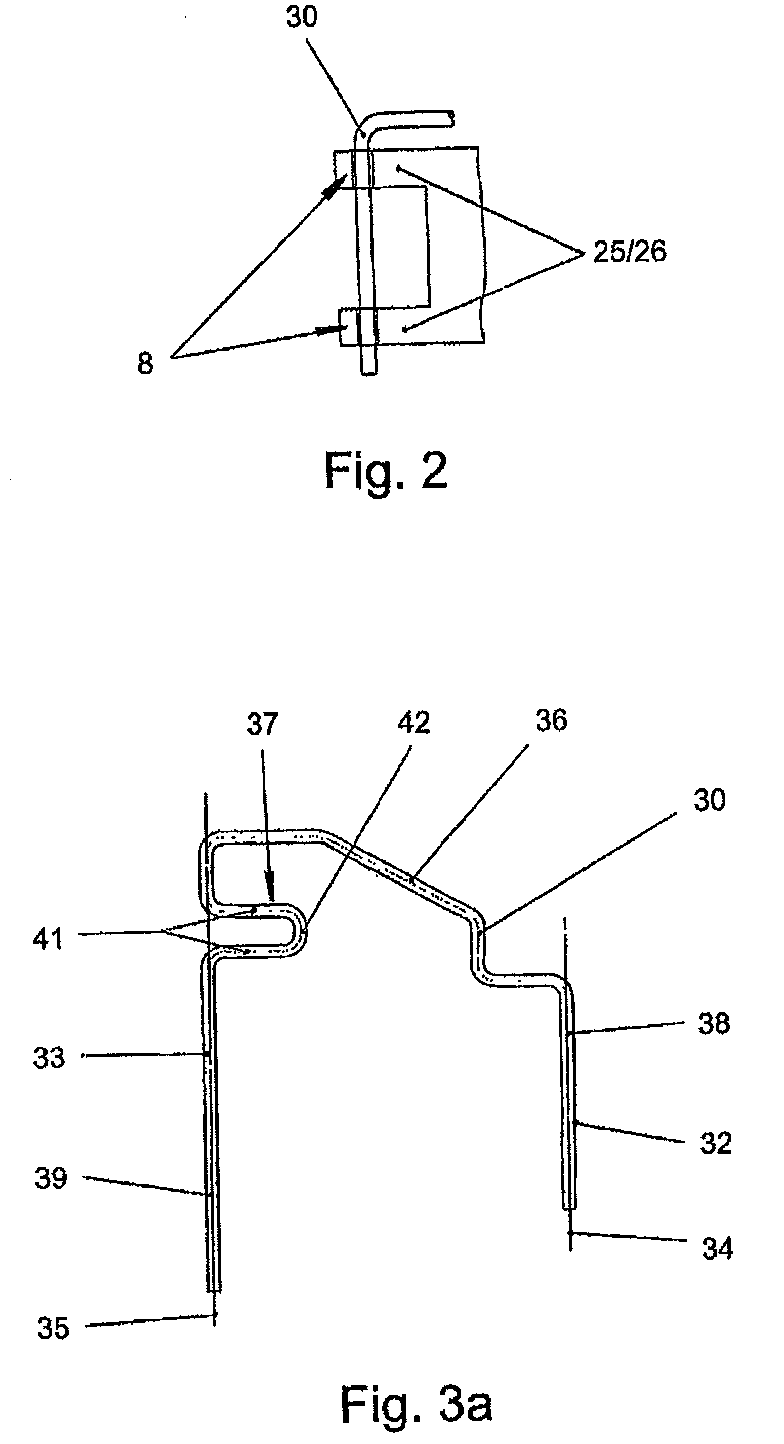
[0027]A mounting space 31 for a retaining clip or hinge clip 30 is provided on the side of mirror head 12 facing mirror foot 11. Mounting space 31 is limited essentially by a front housing wall 17 lying to the fron...


PUM


Abstract

In some embodiments of outer rear-view mirrors, a mirror head (12) and a mirror base (11) are joined together in an articulated manner by a hinge (15, 16). The mirror head (12) can pivot out of a normal operational position in or against the travelling direction (10) and be fixed in the position swivelled against the travelling direction (10). For the outer rear-view mirror to be pivotable out of its normal operational position in or against the travelling direction (10), the intermediate joint (30) has two parallel joint axes arranged between the mirror base and the mirror head, and a U-shaped projection (37). The outer rear-view mirror is advantageously used in motor vehicles.

Description

[0001]This patent application claims priority to a PCT Patent Application having application number PCT / EP2006 / 004283, claiming priority from a German patent application having application number DE 10 2005 021 757.5, filed on May 11, 2005.BACKGROUND ART[0002]1. Field of the Invention[0003]The invention concerns an outside rear view mirror for motor vehicles. More particularly, the invention concerns an outside rear view mirror having a bidirectional pivot mechanism.[0004]2. Description of the Related Art[0005]Outside rear view mirrors are known in the automotive field in which a mirror head and a mirror foot are hinged to each other on both sides via a hinge. It is possible by means of such a hinge for the mirror head to be pivoted from a normal operating position in or against the direction of travel. It is also known that the mirror head pivoted opposite the direction of travel must be securely locked in this pivoted position. Operation for this purpose can occur both by hand and...

Claims


Application Information

Patent Timeline
Patent Type & Authority Patents(United States)
IPC IPC(8): G02B7/182B60R1/06
CPCB60R1/076Y10S248/90
Inventor OEHMANN, ROLANDSONNTAG, KÜRSAT
Owner SMR PATENTS S A R L
Why Eureka
Try Eureka