Flow limiting drinking straw

a technology of drinking straws and limiting nozzles, which is applied in the field of drinking straws, can solve the problems of inability to control the mouth muscles, facial paralysis, and other motor function problems, and achieve the effects of fast fluid acceleration, rapid sealing of flow, and accurate determination

Active Publication Date: 2015-10-27
HANNERS JENNIFER
View PDF6 Cites 7 Cited by
  • Summary
  • Abstract
  • Description
  • Claims
  • Application Information

AI Technical Summary

Benefits of technology

[0018]In all modes, the valve operationally engaged at the distal end of the straw body, is closed when the user is not sucking on the distal end of the straw. However, at least one aperture allowing fluid to pass through the valve will open gradually as fluid is accelerated through the device by the user sucking from the proximal end. This gradual opening provides a gradually enlarging fluid passage to communicate fluid to the mouth of a user. The gradual opening from closed to larger open positions also provides a means for gradually increasing flow rate of fluid through the valve and means to prevent excess acceleration upon suction by the user on the distal end.
[0019]As such, the axial passage communicating liquid through the body of the straw is provided a fluid flow which is regulated by operation of the valve. The regulation prevents over acceleration of fluid from the straw and caps the fluid flow by volume to a maximum flow rate which is determined by a maximum opening of the valve for communication of fluid therethrough.
[0020]Thus, the valve component operatively engaged with the body of the straw, provides a means for limiting the volume of fluid which can enter the passage of the body in a given period of time at a given suction force imparted by the user. Further, in all modes, the valve means is preferably configured to operate as a one way valve and therefor resist backflow of fluid through the valve and to prevent spillage of fluid from the distal end.
[0025]In this fashion, the acceleration of the fluid stream exiting the straw can be limited not to exceed a certain maximum speed or acceleration, thereby providing a means for fluid acceleration restriction. This prevents a user who imparts excess suction to the distal end of the straw from having fluid accidentally traverse the throat into the lungs from slow reflexes.
[0026]Further, the total potential volume allowed per suction by the user on the straw may be reasonably accurately determined by forming the sealing member of a size and material yielding a density to seat the sealing member against the spaced upper wall and seat, only after a determined period of time, depending on the strength of the user sucking on the straw and the acceleration of the fluid stream. Hard and quick suction by a user will yield faster fluid acceleration and in turn, a faster sealing of the flow since the sealing member will be forced upward quickly to cease flow.
[0027]A softer or lower suction action by a user, will yield a slower acceleration of fluid and slower overall fluid flow thereby determining a longer time segment for the sealing member to rise to the seat if the specific gravity of the sealing member and its exterior dimensions are correctly calculated to cause it to rise in the direction of the fluid stream with minimal fluid acceleration. Further adjustments for volume allowed in any one sucking of the straw may be provided by spacing the distance of the upper wall from the lower wall and thus the total volume of the chamber and resulting total distance the sealing member must travel to seat and cease flow.

Problems solved by technology

Such patients may have suffered from a stroke causing facial paralysis or other motor function problems inhibiting muscular control of the mouth and / or throat.
For patients suffering from facial paralysis affecting one side of their mouths, or causing lack of muscle control, or lack of experience using a straw, there is an inherent risk if they are allowed to ingest the total volume of liquid reaching the distal end of the straw on which they are sucking.
Further, for patients recovering from head trauma or brain trauma, there can be a lack of reflexes as well as lost knowledge on how to swallow and how hard to suck on a straw.
Such patients can suffer severe health problems should fluid from a straw be communicated to the lungs from misuse or lack of ability to use the straw properly.
As such, within the medical realm there exists a population of patients who, because of inexperience with straws or various congenital or acquired physical disorders, have deficient oropharyngeal or oral motor function which impairs their ability to manipulate and transport food and fluids placed in their mouths.
Due to such poor control of the oropharyngeal muscles, such patients may tend to draw too much fluid through a straw, or such patients may have reflexes which are slow to swallow the volume of fluid drawn through the proximal end of the straw which can lead to the fluid being accelerated into the mouth and throat which can cause choking and communication of the fluid to the lungs.
As a result of such inherent or acquired disabilities, many patients are in constant danger of ingesting too much fluid when sucking on a straw to drink or sucking too hard and causing excess acceleration of the discharge of the fluid to their mouths.
Whether there is an excess of fluid or fluid discharging to the mouth at high acceleration, many patients are just unable to effectively swallow the volume of fluid naturally drawn into their mouths.
Excess fluid volume or over accelerated fluid can result in the patient losing the drawn fluid out of their mouth or nose through choking or coughing, thereby yielding an embarrassing occurrence.
Worse yet, patients who ingest too much in a suck of the straw or fail to dispose of the fluid from the nose or mouth during choking may suffer from passage of the fluid into their lungs.
Communication of such fluid to the lungs can result in respiratory arrest, or more often, a lung infection from fluid being deposited in their lungs.
However, the device to Pearson relies solely on an insoluble object to properly seal the conduit from further fluid flow in the event of excessive volume suction or acceleration of fluid through the straw.
Pearson does not teach any means for regulating fluid volumetric flow rate into the compartment as may be needed to further regulate and control fluid flow through the straw.
Various limitations of the related art will become apparent to those skilled in the art upon a reading and understanding of the specification below and the accompanying drawings.

Method used


Image

  • Flow limiting drinking straw
  • Flow limiting drinking straw

Examples


Embodiment Construction

[0041]In this description, the directional prepositions of up, upwardly, down, downwardly, front, back, top, upper, bottom, lower, left, right and other such terms refer to the device as it is oriented and appears in the drawings and are used for convenience only; they are not intended to be limiting or to imply that the device has to be used or positioned in any particular orientation.

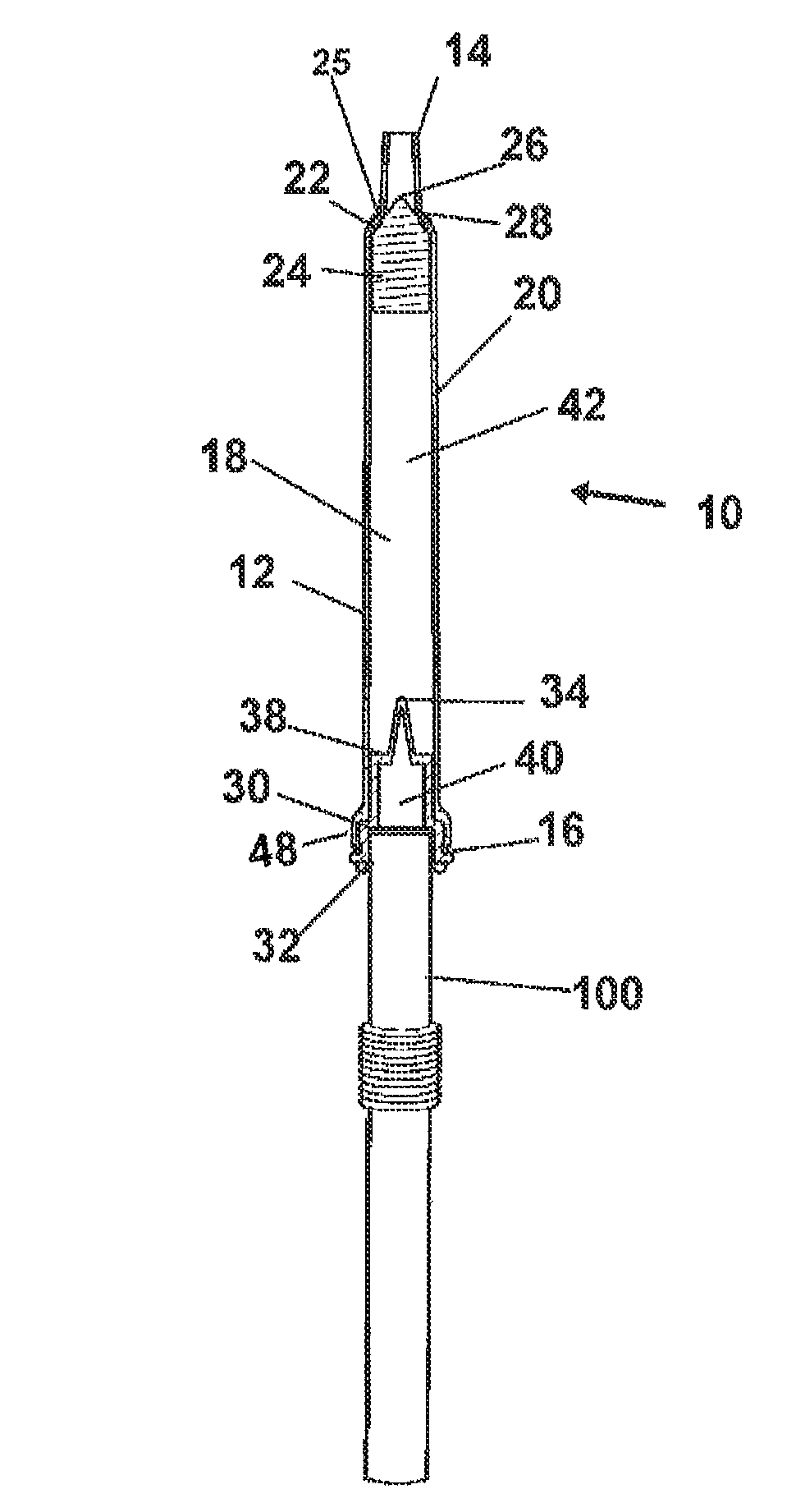
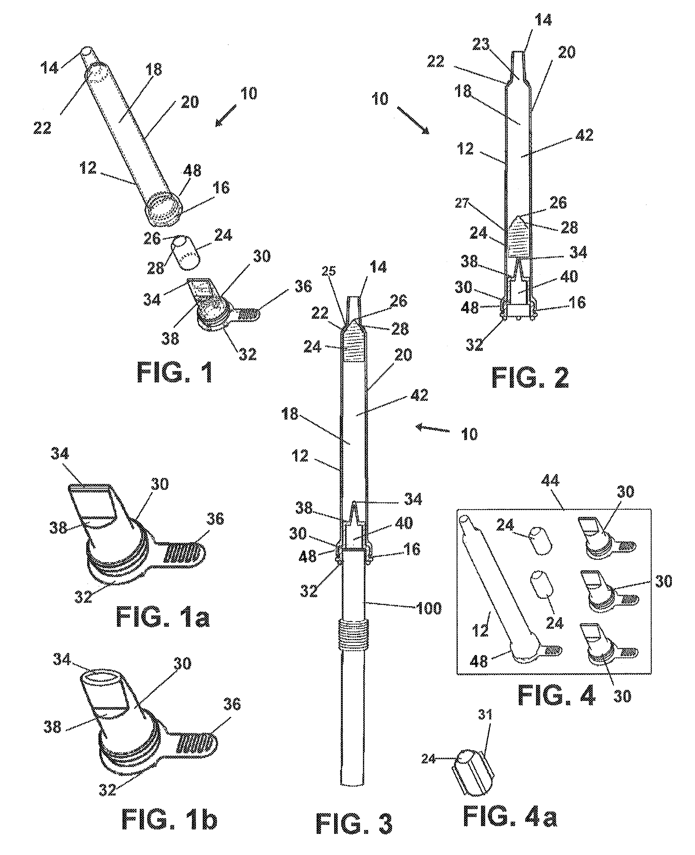
[0042]Now referring to drawings in FIGS. 1-4, wherein similar components are identified by like reference numerals, there is seen in FIG. 1 an exploded view of a first preferred mode of the straw device 10 herein. The device 10 is comprised generally of an elongated body 12 having apertures at proximal 14 and distal 16 ends communicating through an axial passage 42 communicating therebetween. The body 12 is preferably formed from conventional materials such as plastic, polymeric material, or metal, however can be formed from any material suitable for the intended purposes set forth in this disclosure....


PUM


Abstract

A fluid flow regulating component adapted for sealed engagement to a drinking straw is provided to prevent excess fluid flow to users drinking with a straw. The device has a body adapted to engage the straw at one end to direct fluid flow through an axial cavity to an exit aperture. A translating valve body within the axial cavity ceases fluid flow during periods of excess acceleration or volume. A secondary valve may be engaged to prevent backflow of the fluid.

Description

[0001]This application claims priority to U.S. Provisional Patent Application Ser. No. 61 / 749793, filed on Jan. 7, 2013, and incorporated herein in its entirety by this reference thereto.BACKGROUND OF THE INVENTION[0002]1. Field of the Invention[0003]The present invention relates generally to drinking straws. More particularly, the invention relates to a straw device for consumption of liquids from a reservoir in a vessel, which provides a means for regulating fluid flow of fluid volume, velocity, and acceleration, on exit from the proximal end of the straw during which suction is imparted by a user. The device is removably engageable to conventional straws without the need to modify the existing straw or can be formed as a unitary structure.[0004]2. Prior Art[0005]Drinking straws are a convenient way to drink fluids from containers and in some instances may be a necessity for certain individuals such as hospital patients, children, the elderly, disabled persons, and others. While s...

Claims


Application Information

Patent Timeline
Patent Type & Authority Patents(United States)
IPC IPC(8): A47G21/18A61J7/00
CPCA47G21/185A47G21/18A61J7/0038
Inventor HANNERS, JENNIFER
Owner HANNERS JENNIFER
Why Eureka
Try Eureka