Inertial igniters with safety pin for initiation with low setback acceleration

Inactive Publication Date: 2011-12-08
OMNITEK PARTNERS LLC
View PDF36 Cites 6 Cited by
  • Summary
  • Abstract
  • Description
  • Claims
  • Application Information

AI Technical Summary

Benefits of technology

[0009]Accordingly, an inertial igniter is provided. The inertial igniter comprising: a mass element; a base element; a spring element connecting the mass element and the base element; and a safety m

Problems solved by technology

The electrolyte is dry, solid and non-conductive, thereby leaving the battery in a non-operational and inert condition.
The process of manufacturing thermal batteries is highly labor intensive and requires relatively expensive facilities.
Fabrication usually involves costly batch processes, including pressing electrodes and electrolytes into rigid wafers, and assembling ba

Method used


Image

  • Inertial igniters with safety pin for initiation with low setback acceleration
  • Inertial igniters with safety pin for initiation with low setback acceleration
  • Inertial igniters with safety pin for initiation with low setback acceleration

Examples


Example

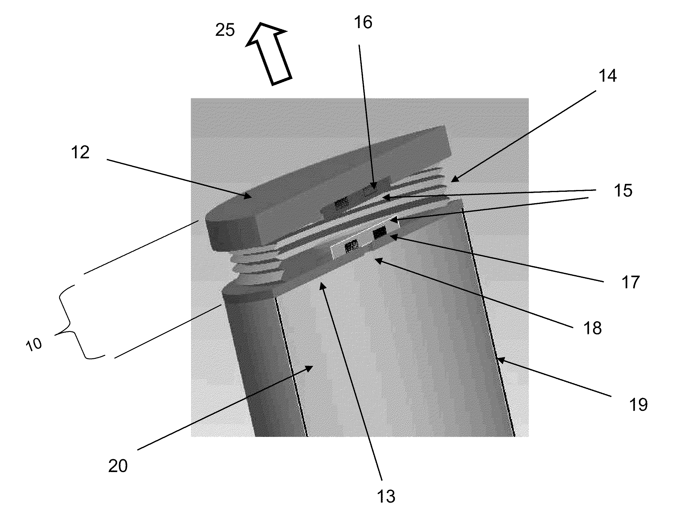
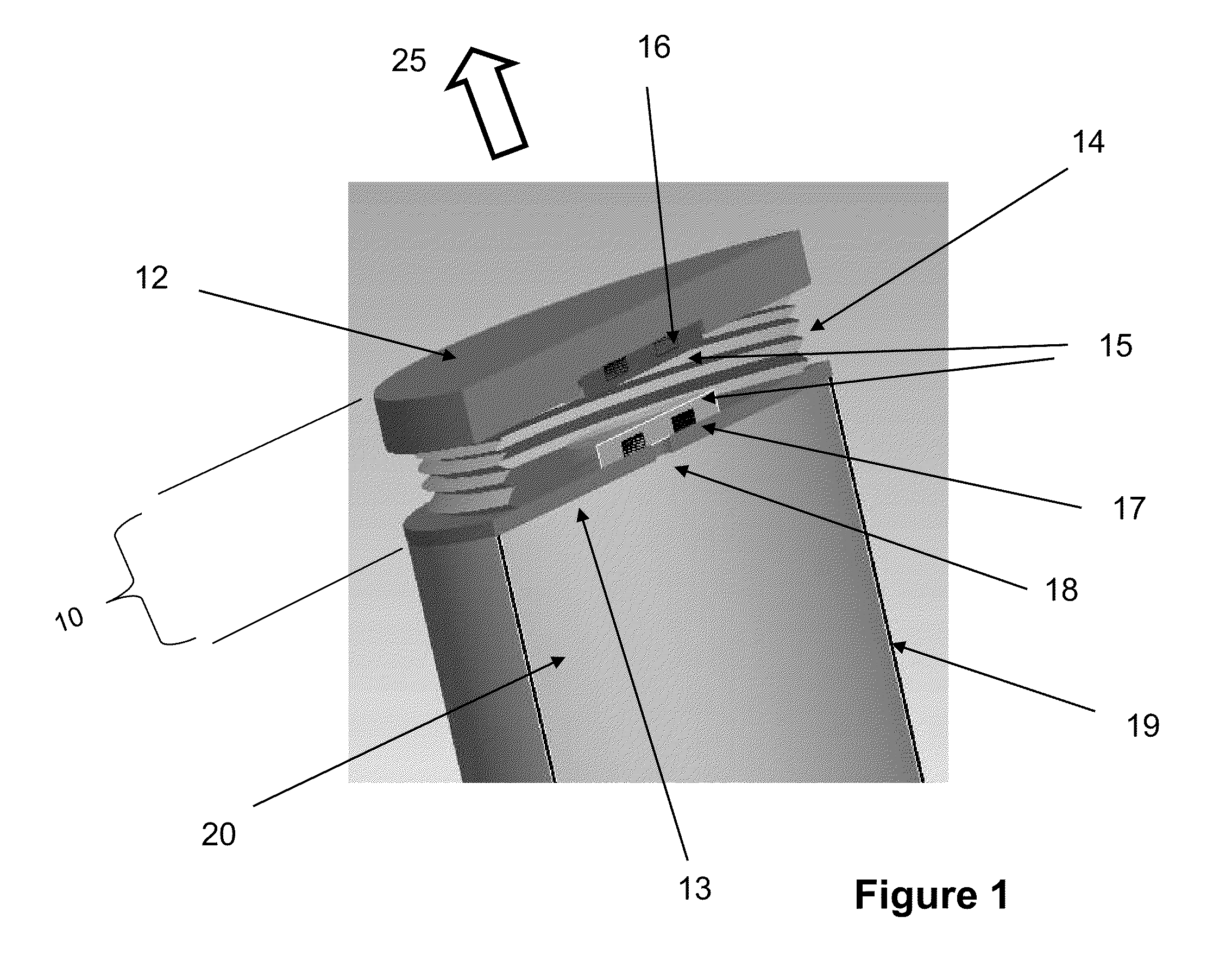
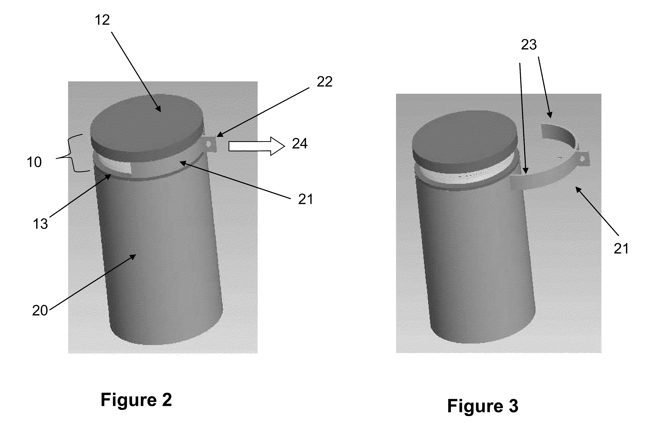
[0025]The schematic of a first embodiment is shown in the frontal cross-sectional view of FIG. 1. In FIG. 1, the inertial igniter 10 is shown to be fixed to the top of the thermal battery 11. The inertial igniter 10 is shown to consist of a top cap 12, which also acts as a striker mass for initiating ignition during all-fire conditions. The top cap 12 is attached (such as being welded or brazed) to the base plate 13 by a bellow 14, which can be stainless steel or other suitable material. The base plate 13 can be the top cap of the thermal battery 20 and is attached (such as being welded or brazed) to the thermal battery housing 19. The base plate 13 can be fabricated with stainless steel. The top cap 12 can be made out of a one piece stainless steel material. The top cap 12 may also be constructed with two piece elements (not shown in FIG. 1), with an outer shell of stainless steel (to make it easier to weld to the bellow 14) and an interior (in the present design disc shaped) eleme...


PUM


Abstract

Inertial igniters for initiating a thermal battery and methods of preventing initiation of an inertial igniter are provided. The method including: biasing a mass element from a base element with a spring element connecting the mass element and the spring element; and removably disposing a safety member between the mass element and the base element to prevent relative movement between the mass element and base element to prevent accidental initiation of the inertial igniter. The method can further comprise removing the safety member prior to subjecting the inertial igniter to all-fire conditions.

Description

CROSS-REFERENCE TO RELATED APPLICATIONS[0001]This application claims benefit to U.S. Provisional Application No. 61 / 184,787 filed on Jun. 6, 2009, the entire contents of which is incorporated herein by reference.BACKGROUND OF THE INVENTION[0002]1. Field of the Invention[0003]The present invention relates generally to inertial igniters for thermal batteries or other pyrotechnic type initiated devices for munitions, such as rockets, with low setback accelerations and equipped with safety pins.[0004]2. Prior Art[0005]Thermal batteries represent a class of reserve batteries that operate at high temperatures. Unlike liquid reserve batteries, in thermal batteries the electrolyte is already in the cells and therefore does not require a distribution mechanism such as spinning. The electrolyte is dry, solid and non-conductive, thereby leaving the battery in a non-operational and inert condition. These batteries incorporate pyrotechnic heat sources to melt the electrolyte just prior to use in...

Claims


Application Information

Patent Timeline
IPC IPC(8): F42C15/18
CPCF42C15/20
Inventor RASTEGAR, JAHANGIR S.MURRAY, RICHARD T.
Owner OMNITEK PARTNERS LLC
Why Eureka
Try Eureka