Cosmetic applicator

a technology of mascara brush and applicator, which is applied in the field of cosmetic applicators, can solve the problems of cumbersome use of the applicator, not all users are adept at being able to gradually twist their wrists, and cannot achieve the desired effect with a single mascara brush

Active Publication Date: 2011-12-08
ZEN DESIGN SOLUTIONS
View PDF27 Cites 33 Cited by
  • Summary
  • Abstract
  • Description
  • Claims
  • Application Information

AI Technical Summary

Benefits of technology

[0013]According to yet another embodiment of the invention the cosmetic applicator imitates the twirl of the wrist during application and thereby provides an expert like application even by a novice at make-up skills.

Problems solved by technology

However, all the desired effects are not possible with a single mascara brush.
Further, a user requires twisting and / or turning his / her hands in a particular manner to achieve a particular desired effect on the lashes and not all users are adept in being able to gradually twist their wrist along with the outward stroke of application on the lashes.
However, the usage of these applicators is cumbersome for the user and some users find it frightening to use the battery-powered applicators.
If the product is applied using the aforementioned applicators then during application on the lashes the application brush would be followed subsequently by the comb part or vice versa and the user is expected to gradually blend the application with multiple such strokes, however, this creates a stark application.

Method used


Image

  • Cosmetic applicator
  • Cosmetic applicator
  • Cosmetic applicator

Examples


Embodiment Construction

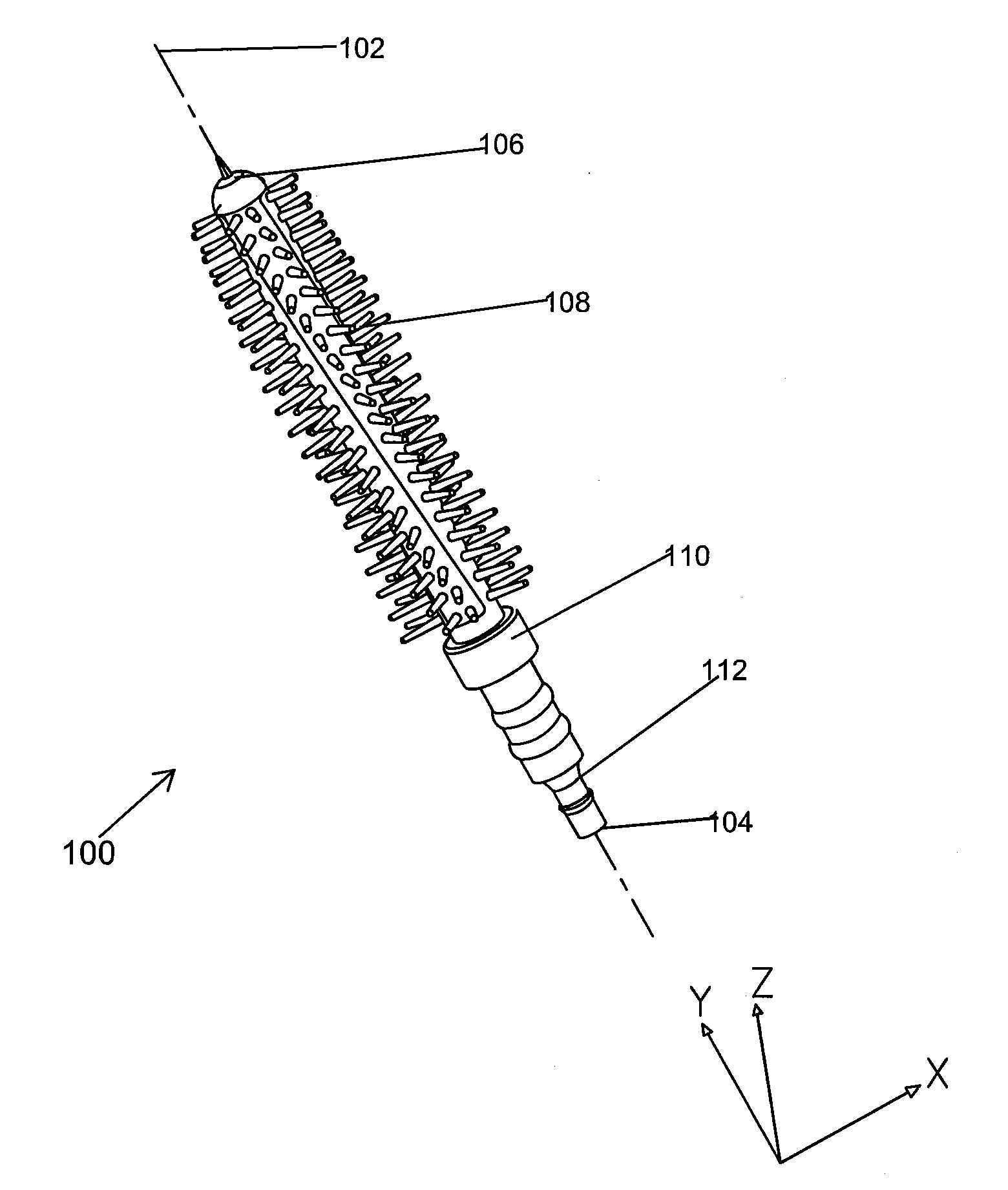
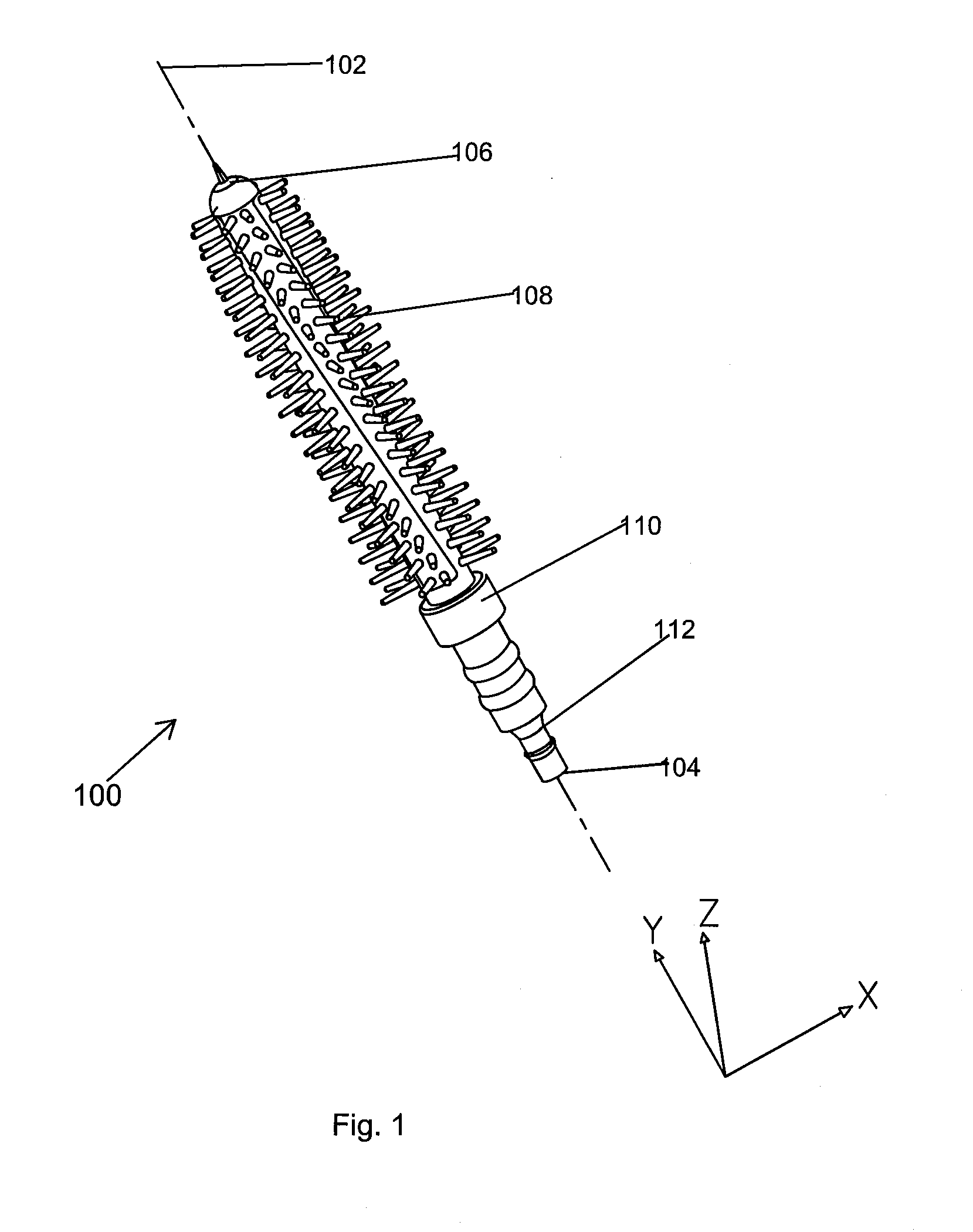
[0037]The applicator according to one embodiment of the present invention is shown in FIGS. 1 to 6.

[0038]FIG. 1 is one embodiment of the present invention showing an isometric view of a molded applicator 100. The applicator 100 is elongated along a center line 102 (e.g., the centre longitudinal axis), extending from proximate end 104 to a distal end 106. The applicator 100 includes an applicator tip 108 separated by a base 110 from a mounting portion 112. A portion of the center line 102 extending through the base 110 and mounting portion 112 may be linear, while a portion of the center line 102 extending through the applicator tip 108 may be linear, curved or have another geometry. In the embodiment depicted in FIG. 1, the center line 102 passes linearly through the base 110, applicator tip 108 and mounting portion 112.

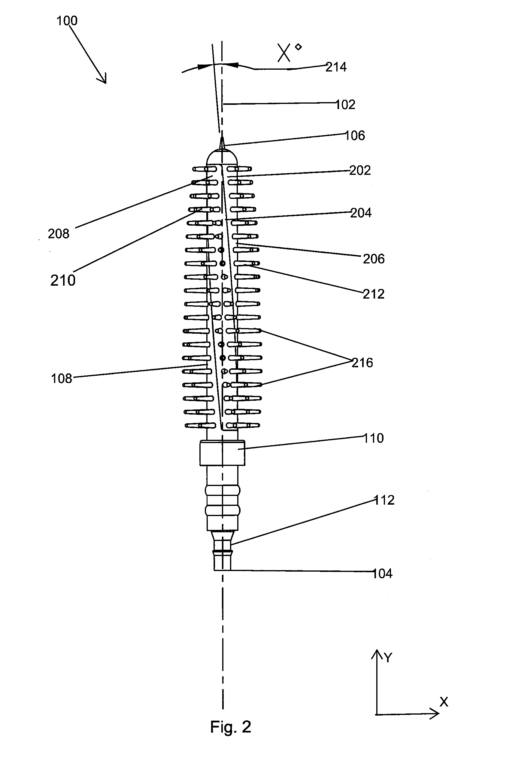
[0039]FIG. 2 is a front view of the applicator 100 illustrating the applicator tip 108 in greater detail. The applicator tip 108 is elongated (in the y-direction) an...


PUM


Abstract

The present invention generally relates to a cosmetic applicator and in particular, relate to a cosmetic applicator comprising of at least two molded applicator parts that are interlinked such that a non-zero angle is formed at an interface of the at least two molded applicator parts with respect to a centerline of the applicator. The cosmetic applicator of present invention imitates the twirl of the wrist during application and thereby provides a better application. The cosmetic applicator of the present invention may be used for cosmetic and care applications such as mascara application, hair coloring, lip application, etc.

Description

CROSS-REFERENCE TO RELATED APPLICATION[0001]This application claims benefit of U.S. Provisional Application Ser. No. 61 / 351,503, filed Jun. 4, 2010, which is incorporated by reference in its entirety.BACKGROUND[0002]1. Field of the Invention[0003]Embodiments of the present invention generally relate to a cosmetic applicator and in particular, relate to a cosmetic applicator comprising of at least two molded applicator parts that are interlinked such that a non-zero angle is formed at an interface of the two molded applicator parts with respect to a centerline of the applicator. The cosmetic applicator of present invention is able to imitate the twirl of the wrist during application and thereby provides a better application. The cosmetic applicator of the present invention may be used for cosmetic and care applications such as on skin or on keratinous fibers in the area of mascara application, lash care, nail care, mascara removal, lip application, hair coloring and hair repair etc.[...

Claims


Application Information

Patent Timeline
Patent Type & Authority Applications(United States)
IPC IPC(8): A45D40/26A46B9/02
CPCA45D34/045A45D40/265A46B2200/1053A46B9/021A46B11/06A46B3/005
Inventor PIRES, LEO CLIFFORDHWANG, ROGERBOSE, RAHULKOHLI, MANISHA
Owner ZEN DESIGN SOLUTIONS
Why Eureka
Try Eureka