Adjustable foot, in particular a rear foot, for an electric household appliance

a technology for electric household appliances and rear feet, which is applied in the direction of machine supports, cleaning equipment, tableware washing/rinsing machine details, etc., can solve the problems of thread sticking or damage, cumbersome solutions, and complex solutions, and achieves cost-effective construction, small size, and simple

Active Publication Date: 2011-12-08
ILLINOIS TOOL WORKS INC
View PDF4 Cites 13 Cited by
  • Summary
  • Abstract
  • Description
  • Claims
  • Application Information

AI Technical Summary

Benefits of technology

[0003]It is an object of the present invention to solve the aforesaid problem by providing a height-adjustable foot for an electric household appliance which has a simple, cost-effective construction, is small in size, very reliable, and which allows to obtain a slipping at the stroke-end when lifting the foot, which avoids the thread from being forced by applying extra-torque on the worm screw by the user, which is minimum and in all cases much less than that needed in the known solutions.

Problems solved by technology

Such a type of height-adjustment device for the foot has the problem of managing the stroke-end, when the foot is raised; indeed, the foot is usually arranged behind the electric household appliance but is controlled from the front, e.g. by means of a tool inserted through a hole of the front panel, whereby it may not be seen.
Sticking or damages to the thread may occur if the user applies a torque on the worm screw at the stroke-end, without considering the excessive effort required by the user when manoeuvring.
However, such a solution is complex, cumbersome and requires the user to apply a high torque for controlling the worm screw.

Method used


Image

  • Adjustable foot, in particular a rear foot, for an electric household appliance
  • Adjustable foot, in particular a rear foot, for an electric household appliance
  • Adjustable foot, in particular a rear foot, for an electric household appliance

Examples


Embodiment Construction

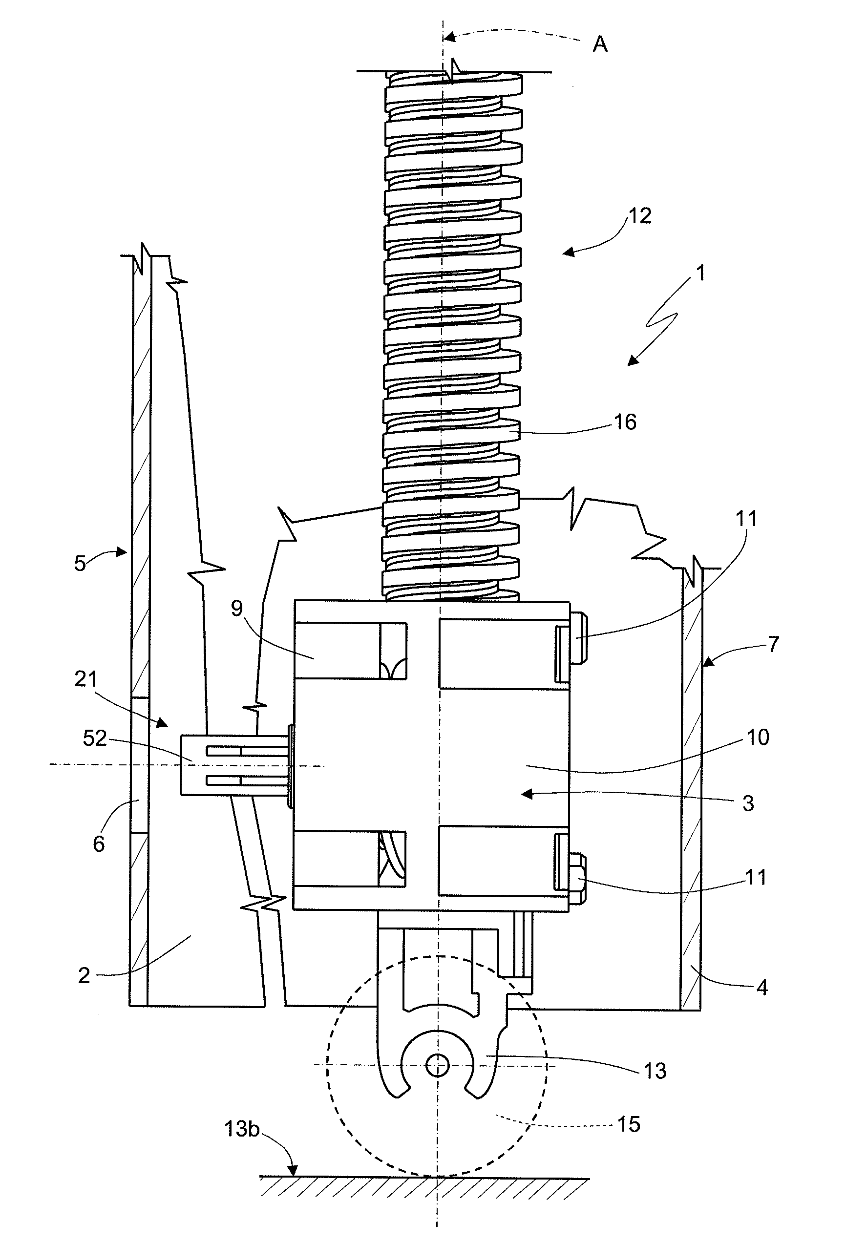
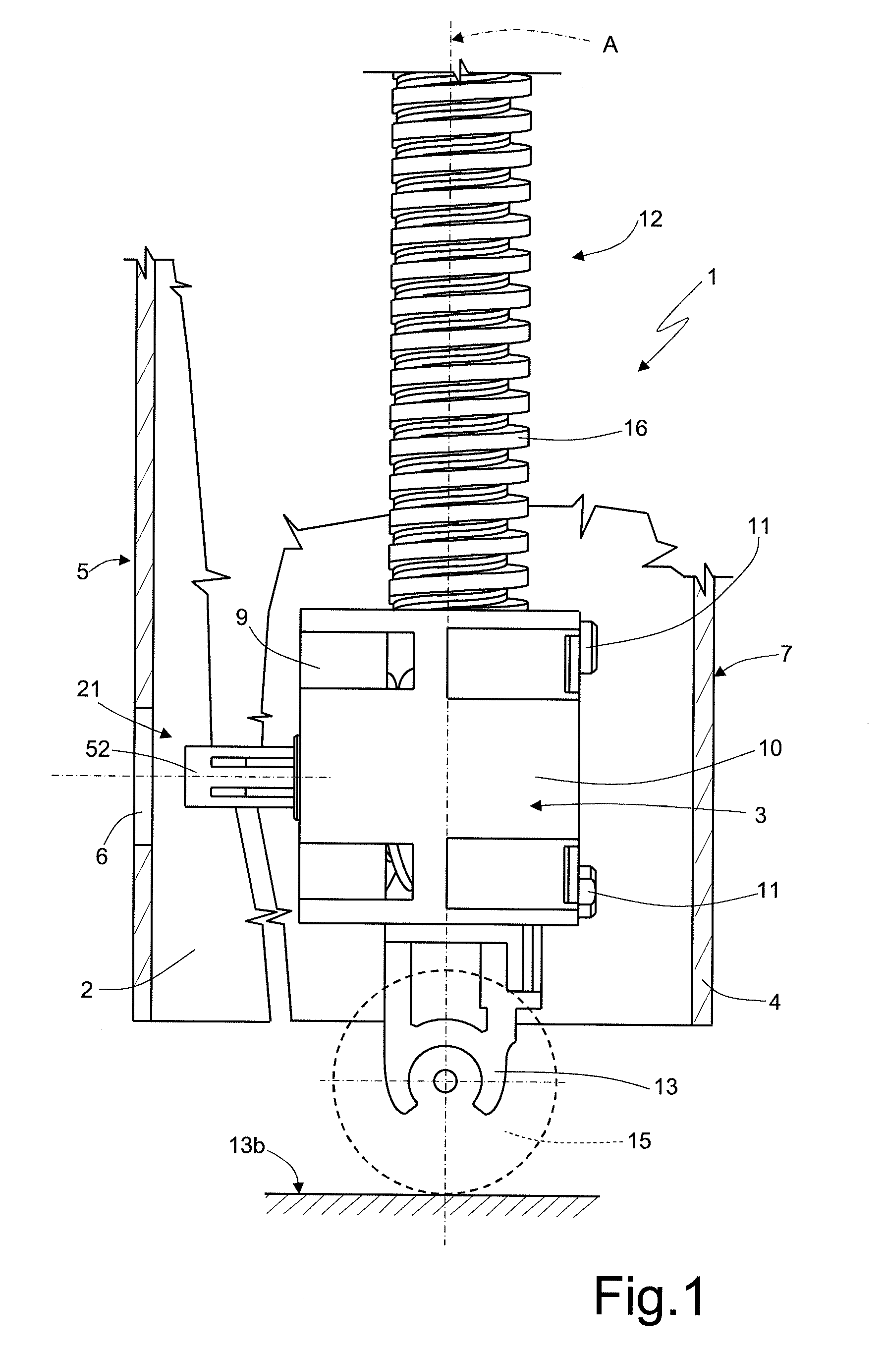
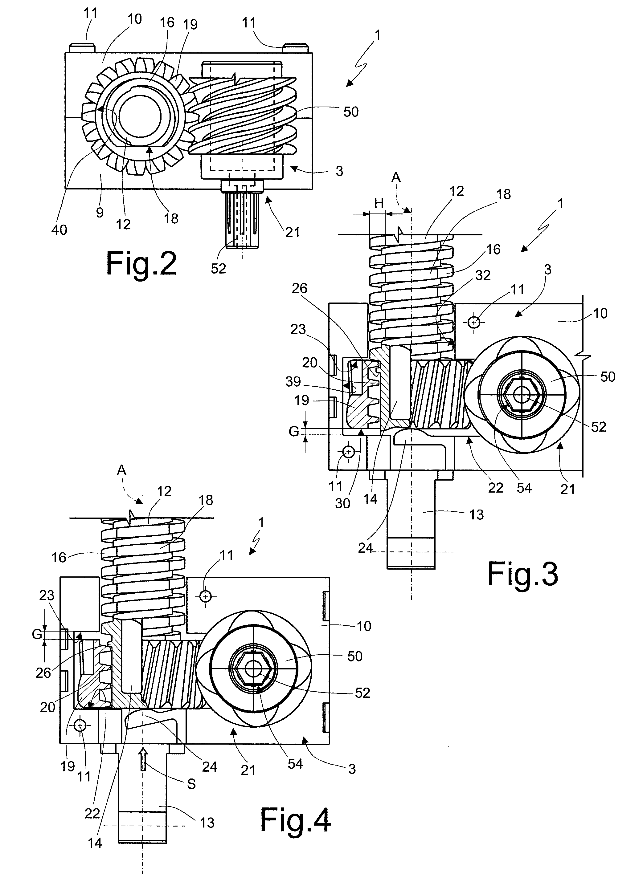
[0014]With reference to figures from 1 to 4, numeral 1 indicates as a whole an adjustable foot for an electric household appliance 2, in particular a rear foot for a fitted washing machine or dishwasher.

[0015]Foot 1 comprises a body 3 integrally fastenable to a casing 4 of the electric household appliance, which has a front panel 5 provided with a hole 6 for actuating the foot 1 by means of an appropriate stem-like tool, of known type and not shown for simplicity, while foot 1 is arranged at a rear panel 7. In particular, body 3 is made by coupling two half-shells 9,10 by means of screws 11 and is made by moulding a synthetic plastic material.

[0016]Foot 1 further comprises a stem 12 vertically carried by the body 3, resting means 13 on a floor 13b associated with a lower end 14 (FIGS. 3,4) of the stem 12 and possibly provided with a wheel 15, first screw means 16 operatively associated with the stem 12 and provided with anti-rotation means 18 cooperating with the body, a toothed whe...


PUM


Abstract

An adjustable foot including a body integrally fastenable to a casing of the electric household appliance, a stem slidingly carried by the body, floor resting means, first screw means operatively associated with the stem and provided with anti-rotation means, a toothed wheel carried by the body so as to be coaxial to the stem and idle about a substantially vertical symmetry axis of the latter, second screw means operatively associated with the toothed wheel and cooperating with the first screw means for vertically translating the stem in response to a rotation of the toothed wheel, and control means for the toothed wheel; wherein the toothed wheel is axially mounted with clearance between opposite first and second abutting means of the body; the latter being provided with elastic axial biasing means cooperating with the toothed wheel and arranged on the side opposite to the end length of the first screw means, which has a thread height gradually decreasing towards the elastic means.

Description

TECHNICAL FIELD[0001]The present invention relates to an adjustable foot, in particular a rear foot, for an electric household appliance. Such a type of foot is usually used in electric household appliances, especially of the fitted type, such as washing machines and / or dishwashers, for both levelling the electric household appliance and possibly moving it, e.g. for maintenance interventions or cleaning.BACKGROUND ART[0002]An adjustable foot is known from EP-A-1895040, for example, in which a stem provided with floor resting means and an external threading meshes with a nut screw obtained inside a toothed wheel, which is rotationally actuated by a worm screw which is controllable by the user. Such a type of height-adjustment device for the foot has the problem of managing the stroke-end, when the foot is raised; indeed, the foot is usually arranged behind the electric household appliance but is controlled from the front, e.g. by means of a tool inserted through a hole of the front p...

Claims


Application Information

Patent Timeline
Patent Type & Authority Applications(United States)
IPC IPC(8): D06F39/00A47L15/42
CPCD06F39/125A47L15/4253
Inventor GENNARETTI, LUCACARLI, PIERLUIGI
Owner ILLINOIS TOOL WORKS INC
Why Eureka
Try Eureka