

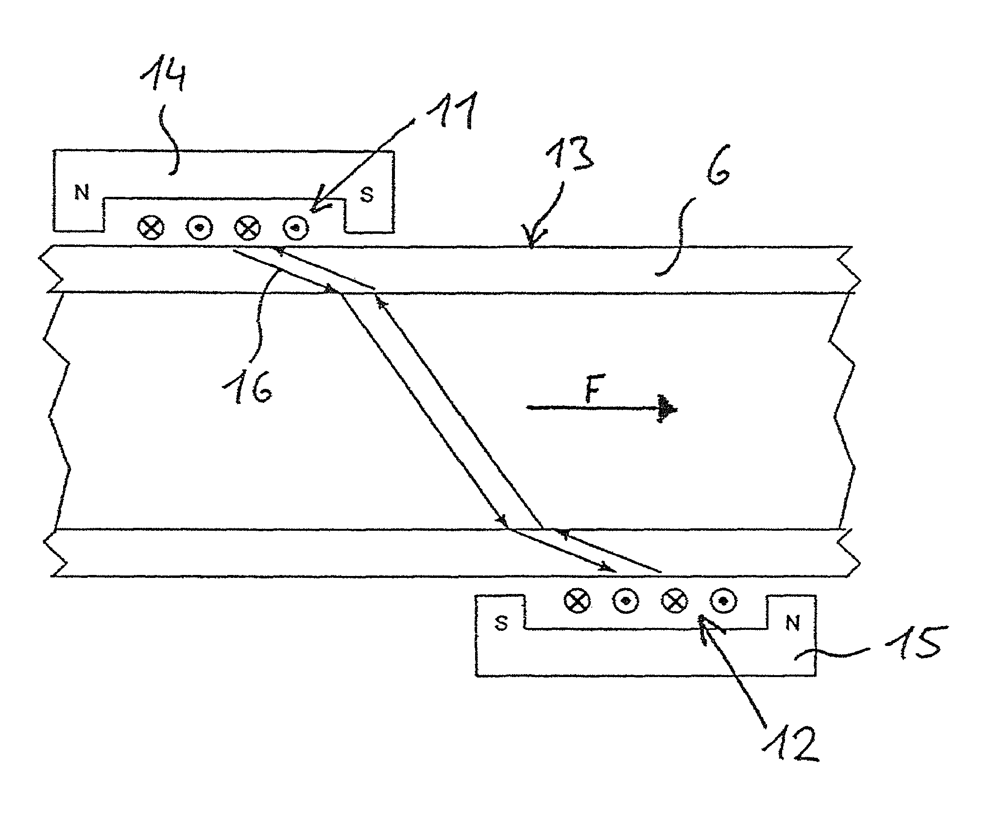
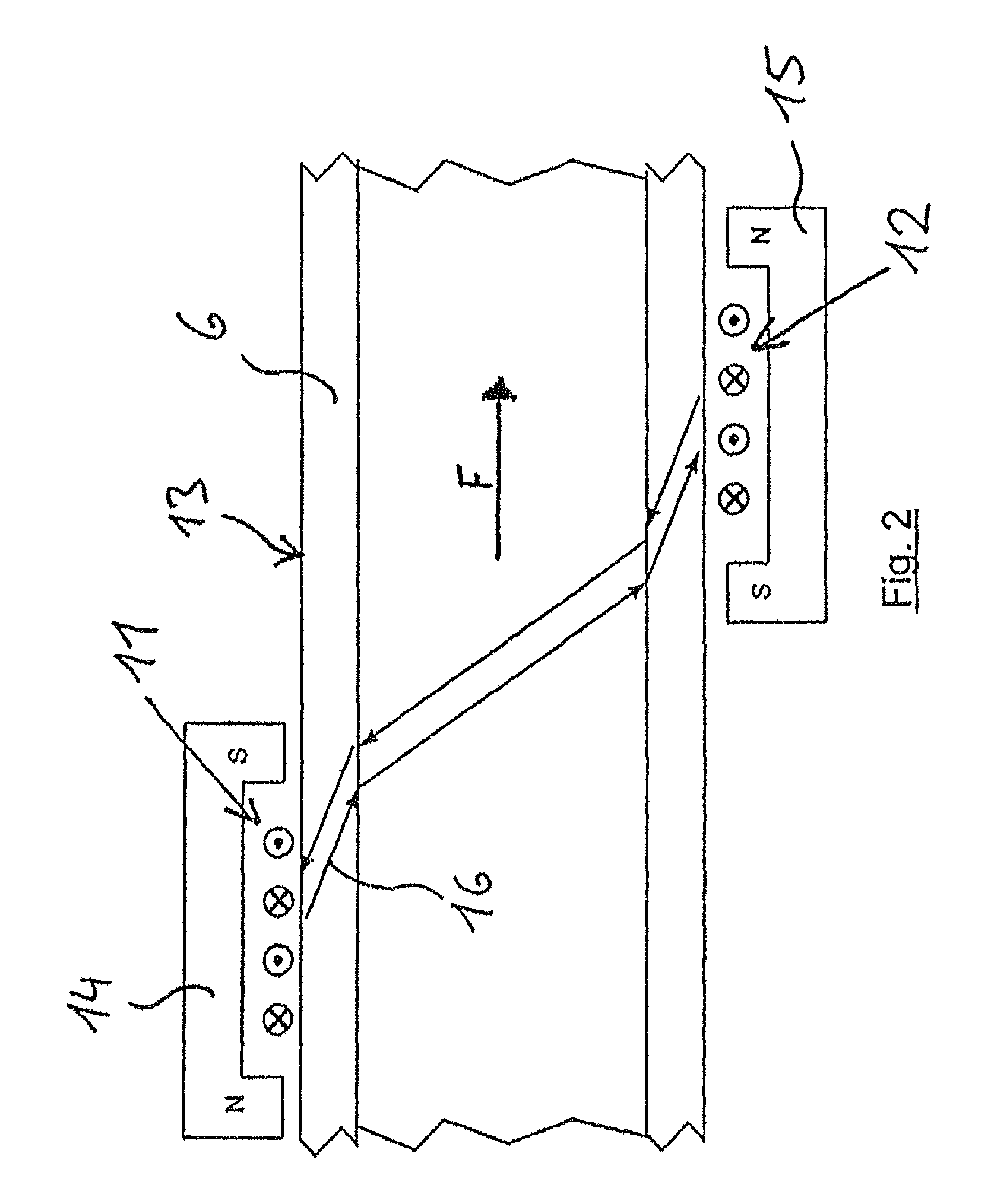
Acoustic flow rate meter having a high frequency induction coil mounted directly on the piping without an acoustic coupling
a flow rate meter and high frequency induction coil technology, applied in the field of acoustic flow rate meters, can solve the problems of not being able to meet the requirements of acoustic coupling, the signal is significantly worse, and the temperature range of conventional ultrasonic flow rate meters is only comparatively narrow, so as to achieve the effect of reducing the effort for a rapid measurement on a variety of already wrapped pipes
- Summary
- Abstract
- Description
- Claims
- Application Information
AI Technical Summary
Benefits of technology
Problems solved by technology
Method used
Image

Examples
Embodiment Construction
[0055]In the following detailed description numerous specific details are set forth in order to provide a thorough understanding of the invention. However, it will be understood by those skilled in the art that the present invention may be practiced without these specific details. For example, the invention is not limited in scope to the particular type of industry application depicted in the figures. In other instances, well-known methods, procedures, and components have not been described in detail so as not to obscure the present invention. Identical or similarly acting parts are provided—if useful—with identical reference signs. Individual technical features of the exemplary embodiments described hereafter can also result in refinements according to the invention with the features of the above-described exemplary embodiments.
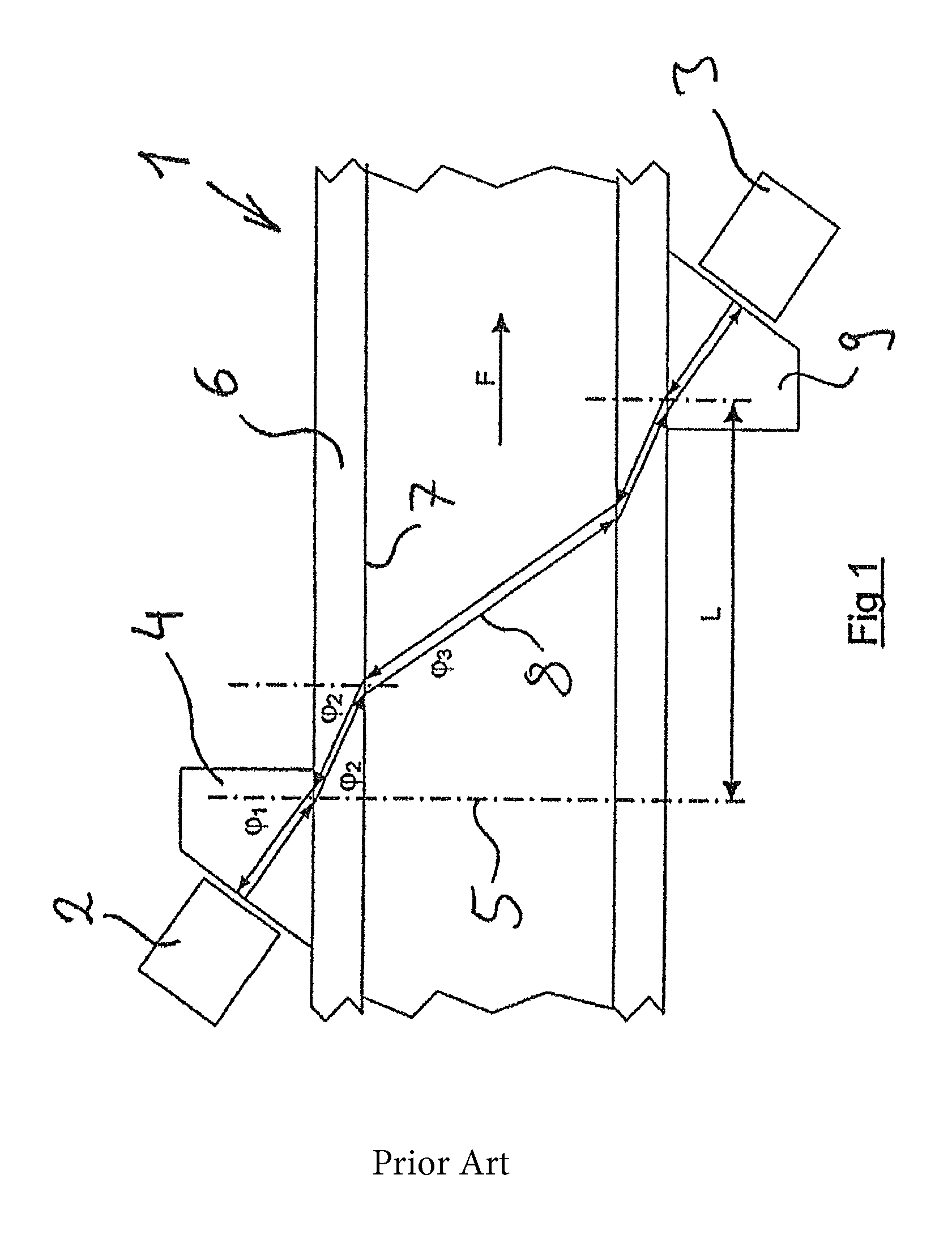
[0056]FIG. 1 shows a setup known from the known prior art for measuring the flow F of a medium, in particular a gas or a liquid, in a pipe 1 illustrated in ...
PUM
 Abstract
Description
Claims
Application Information