

One phase logic
a logic and phase technology, applied in the field of one phase logic, can solve the problems of limiting the rate at which data can be transmitted over the communication link, reducing power consumption, and not being able to eliminate portions of acknowledge circuitry
- Summary
- Abstract
- Description
- Claims
- Application Information
AI Technical Summary
Benefits of technology
Problems solved by technology
Method used
Image

Examples
Embodiment Construction
[0012]Example methods, systems and circuits for providing asynchronous one-phase logic operation, including a pipeline, will now be described. In the following description, numerous examples having example-specific details are set forth to provide an understanding of example embodiments. It will be evident, however, to one of ordinary skill in the art that these examples may be practiced without these example-specific details, and / or with different combinations of the details than are given here. Thus, specific embodiments are given for the purpose of simplified explanation, and not limitation.
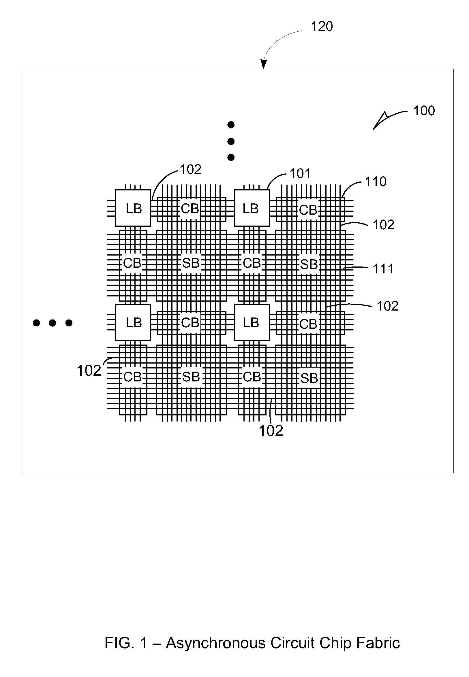
[0013]Asynchronous circuits have a number of advantages compared to their synchronous counterparts when it comes to area, power, and performance. There are a number of different circuit families that can be used to implement asynchronous logic. Embodiments are disclosed pertaining to a family of circuits for asynchronous logic that can improve the performance and reduce the power and area cons...
PUM
 Abstract
Description
Claims
Application Information