Component part mounting structure

Inactive Publication Date: 2011-12-08
HONDA MOTOR CO LTD
View PDF18 Cites 2 Cited by
  • Summary
  • Abstract
  • Description
  • Claims
  • Application Information

AI Technical Summary

Benefits of technology

[0018]Thus, the present invention provides a component mounting structure that can be

Problems solved by technology

However, according to the method proposed in Patent Document 1, the lining has to be cut out before mounting the optional component part, and this requires extra working steps.
The method involving the use of self-tapping s

Method used


Image

  • Component part mounting structure
  • Component part mounting structure
  • Component part mounting structure

Examples


Embodiment Construction

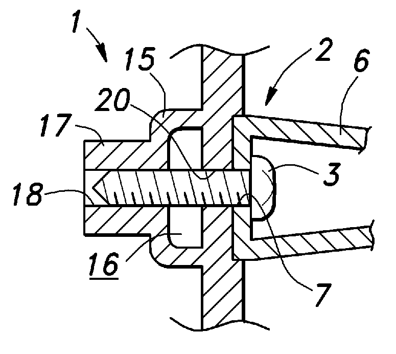
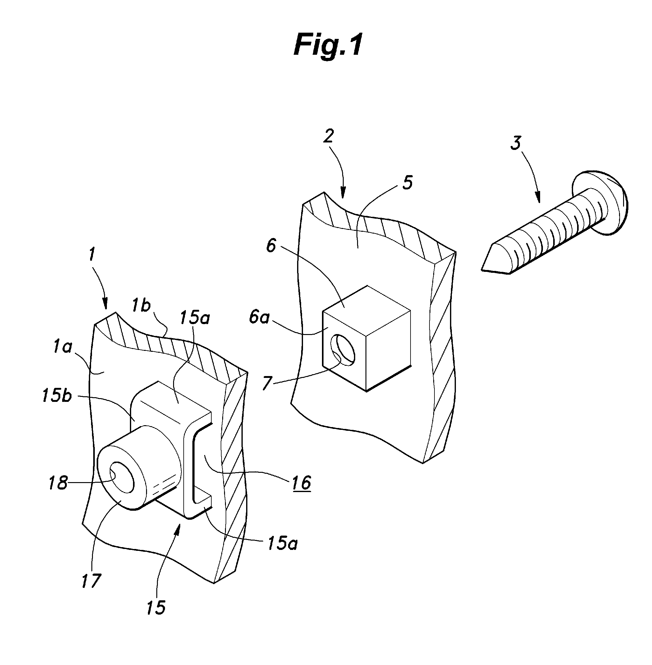
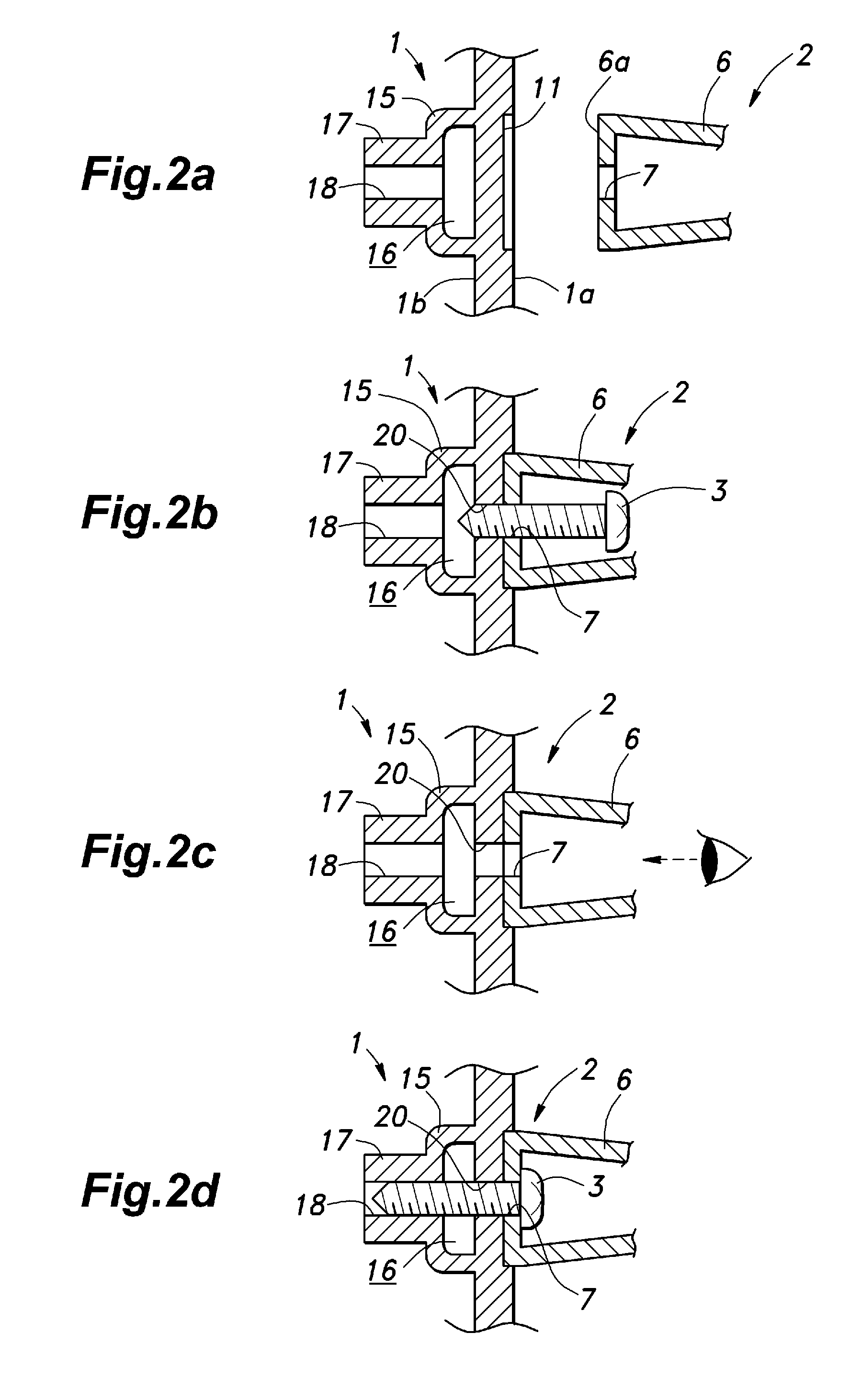
[0022]An embodiment of the present invention applied to a mounting structure for mounting cup holder base 2 to a side lining 1 forming an inner wall of a passenger compartment of a motor vehicle is described in the following with reference to the appended drawings. FIG. 1 is an exploded perspective view showing the component part mounting structure embodying the present invention.

[0023]Referring to FIG. 1, a cup holder base (component part) 2 for supporting a cup holder (not shown in the drawing) is secured to a side lining (upholstery member) 1 by using a self-tapping screw (fastening member) 3. The side lining 1 forms a side wall of a vehicle passenger compartment, and is fixedly secured to a vehicle panel (not shown in the drawings). In the illustrated embodiment, the surface of the side lining 1 facing the interior of the passenger compartment is named as front surface 1a and the surface thereof facing the vehicle body panel is named as rear surface 1b.

[0024]The cup holder base...


PUM


Abstract

A component part mounting structure for mounting a cup holder base (2) on a front surface (1a) of a side lining (1) of a vehicle by using a self-tapping screw (3), wherein the side lining (1) comprises a base portion (15) projecting from a rear surface (1b) of the side lining (1) and defining a space (16) in cooperation with the rear surface (1b), and a boss portion (17) projecting from the base portion and defining a through hole (18) opening out toward the space (16), characterized by that the cup holder base (2) is provided with a fastening seat (6) abutting the front surface (1a) of the side lining (1), and the self-tapping screw (3) is configured to be passed through the fastening seat (6) and side lining (1) from the side of the cup holder base (2), and engaged by the through hole (18) of the boss portion (17) at a free end thereof.

Description

TECHNICAL FIELD[0001]The present invention relates to a component part mounting structure for fastening an optional component part onto a surface of a vehicle upholstery member.BACKGROUND OF THE INVENTION[0002]Oftentimes, an optional component part such as a switch, a loudspeaker and a cup holder is required to be attached to an upholstery member such as a lining (trim) or an instrumental panel that defines an inner wall of a vehicle passenger compartment. Conventionally, when attaching an optional component part onto a lining, a part of the lining is cut out, and the optional component part is fitted into the cutout and fixedly secured therein (see patent document 1, for instance). It is also known to use self-tapping screws to directly secure the optional component part to the lining.PRIOR ART REFERENCESPatent Document(s)[0003]Patent Document 1: JP 06-321022ABRIEF SUMMARY OF THE INVENTIONTask To Be Accomplished By the Invention[0004]However, according to the method proposed in Pat...

Claims


Application Information

Patent Timeline
IPC IPC(8): F16B39/00B23P11/00
CPCB60R11/00B60R13/02B60R2011/0052Y10T29/4978F16B5/02F16B25/00B60R2013/0287
Inventor SATO, TAKAHIROAKABA, SHOGO
Owner HONDA MOTOR CO LTD
Why Eureka
Try Eureka