Assembly and a method for cutting or forming an object

a technology of assembly and object, applied in the direction of stone-like material working apparatus, grinding machine components, grinding/polishing apparatus, etc., can solve the problems of not consistently providing desired surface, requiring a relatively long period of time to perform, and suffering from some drawbacks, so as to reduce the likelihood of undesired structural degradation of the grinding wheel, the effect of reducing the likelihood of undesired structural degradation

Inactive Publication Date: 2006-04-13
MACH WILLIAM
View PDF8 Cites 0 Cited by
  • Summary
  • Abstract
  • Description
  • Claims
  • Application Information

AI Technical Summary

Benefits of technology

[0006] It is a second non-limiting object of the present invention to provide a method and an apparatus for cutting a grinding wheel in a manner which allows desired surface tolerances to be achieved in a consistent, and desirable manner.
[0007] It is a third non-limiting object of the present invention to provide a method and an apparatus for cutting a grinding wheel in a manner which reduces the likelihood of undesired structural degradation while concomitantly producing a grinding wheel having a desired surface finish.
[0008] It is a fourth non-limiting object of the present invention to provide a method and, an apparatus for cutting a grinding wheel in a highly cost effective and efficient manner while concomitantly producing a grinding wheel having a desired-surface finish and reducing the likelihood of undesired structural degradation to the grinding wheel.
[0009] According to a first non-limiting aspect of the present invention a grinding wheel assembly for selectively cutting a grinding wheel is provided. Particularly, the grinding wheel assembly comprises a selectively rotatable cutter; a selectively rotatable grinding wheel support assembly; and a controller assembly which is communicatively and controllably coupled to the cutter and to the grinding wheel and which is effective to cause the cutter to selectively cut the grinding wheel only when the cutter and the grinding wheel are simultaneously and selectively rotated.

Problems solved by technology

While current techniques and strategies do provide the desired working surface on the targeted object, they suffer from some drawbacks.
By way of example and without limitation, these techniques and strategies do not consistently provide desired surface tolerances, undesirably and structurally degrade the object and, in many situations, even cause structural damage to the targeted object, and require a relatively long period of time to perform.
Such “uneven” tolerances will cause the object to perform poorly and such structural degradation may cause the object to be “valueless”, thereby further increasing the cost of the overall process.

Method used


Image

  • Assembly and a method for cutting or forming an object
  • Assembly and a method for cutting or forming an object
  • Assembly and a method for cutting or forming an object

Examples


Embodiment Construction

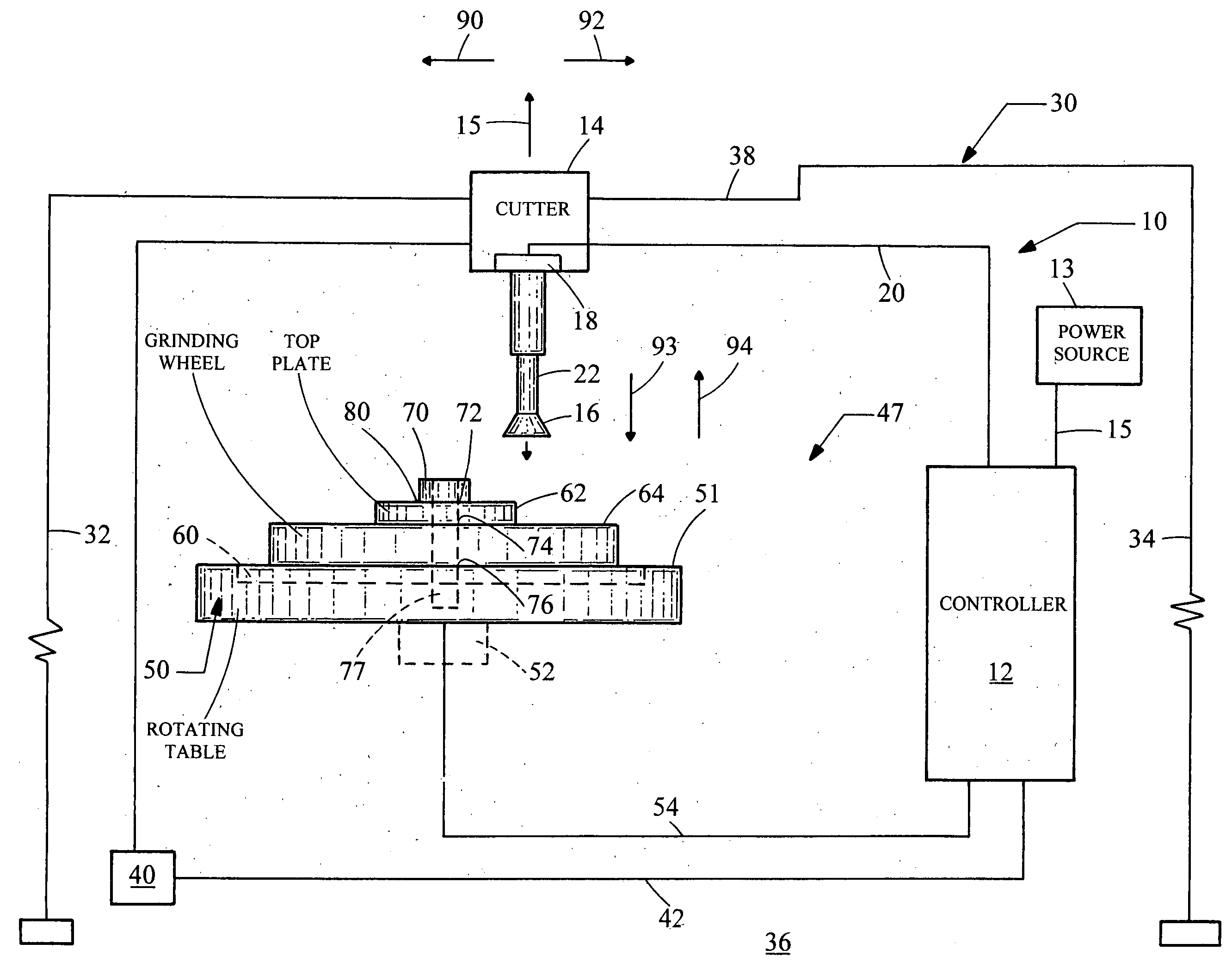
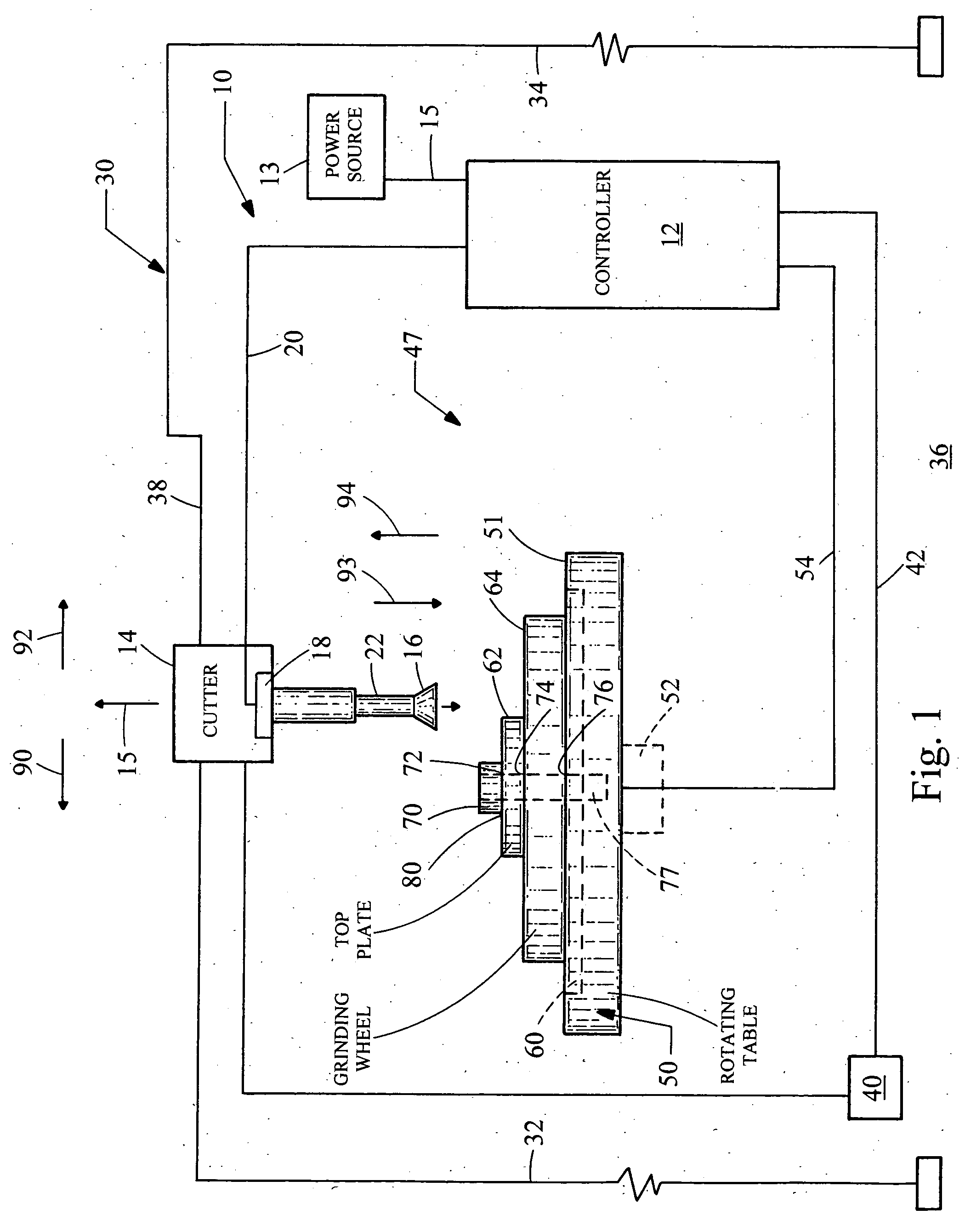
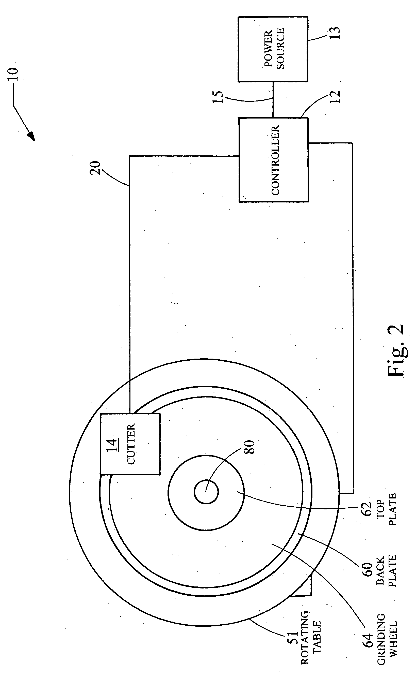
[0018] Referring now to FIGS. 1 and 2, there is shown an assembly 10 which is made in accordance with the teachings of the preferred embodiment of the invention.

[0019] Particularly, the assembly 10 includes a controller 12 which is operable under stored program control and which may, in one non-limiting embodiment, comprise a commercially available and selectively programmable computer, such as a Vaio® type computer which is produced by the Sony® corporation and which includes a Pentium® IV processor. Other types of commercially available and selectively programmable computers may be utilized for controller 12. The controller 12 is physically and communicatively coupled to a source of electrical power 13 by the use of bus 15.

[0020] Further, the assembly 10 includes a cutter assembly 14 including, in the most preferred embodiment of the invention, a selectively removable and selectively rotatable diamond cutting tip portion 16. Further, the cutter assembly 14 includes a motor porti...


PUM

PropertyMeasurementUnit
speedaaaaaaaaaa
symmetryaaaaaaaaaa
lengthaaaaaaaaaa

Abstract

A method and an apparatus 10 for cutting an object 64, such as a grinding wheel. Particularly, the object 64 is placed in a horizontal manner and concomitantly rotated with the cutter 14 during the entire cutting operation. The rotation occurs are a relatively high speed and such concomitant rotation and such horizontal placement allows the cutting to occur in a desired manner.

Description

FIELD OF THE INVENTION [0001] The present invention generally relates to an assembly and a method for cutting or forming an object and more particularly, to a method and an assembly for cutting and / or otherwise “working” and / or forming at least one surface of a grinding wheel or another object. BACKGROUND OF THE INVENTION [0002] An object, such as a grinding wheel, frequently must be cut or “worked / reworked” or “formed” in order to allow the object to achieve a desired working surface finish. By way of example and without limitation, a grinding wheel requires a new working surface finish after some period of usage due to the associated usage wear. This new working surface is typically achieved by selectively cutting or otherwise abrasively engaging the working surface in order to create a relatively smooth finish. It should thus be understood that the terms “working”, “reworking”, “cutting”, and “forming” in this Application, all describe the process of creating a desired and relati...

Claims


Application Information

Patent Timeline
Patent Type & Authority Applications(United States)
IPC IPC(8): B28D1/18
CPCB24B49/00B24B53/00
Inventor MACH, WILLIAM
Owner MACH WILLIAM
Why Eureka
Try Eureka