Wireless antenna module and method for producing same

a technology of wireless antennas and antenna modules, applied in the direction of resonant antennas, manufacturing tools, protective materials radiating elements, etc., can solve the problems of structural constraints, inability to achieve high transmission efficiency, and impaired aesthetic appearan

Inactive Publication Date: 2014-01-09
NISSHA PRINTING COMPANY +1
View PDF2 Cites 6 Cited by
  • Summary
  • Abstract
  • Description
  • Claims
  • Application Information

AI Technical Summary

Benefits of technology

[0052]In the wireless antenna module and the method for producing the wireless antenna module according to the present invention, by providing the top plate in advance in a position of the front surface where the conduction terminal on the back surface side corresponds on the front surface side in the above-described manner, the occurrence of shape failures (sink marks) in a top surface of the housing upon curing a resin can be suppressed.

Problems solved by technology

For example, when an electrode connected to an antenna from the front side of a housing of an antenna module is provided, an aesthetic appearance is impaired.
In particular, power transmission of an electric field coupling scheme is performed between the antenna on the front side of the portable terminal and the contactless contact on the back side across the thickness of the housing, and thus, high transmission efficiency cannot be obtained.
Furthermore, there is also a structural constraint on how to provide a contact for extracting signals from the antenna provided on the front side in the portable terminal.
For example, when an electrode connected to an antenna from the front side of the housing of the antenna module is provided, an aesthetic appearance is impaired.
In addition, performing double molding as described in Japanese Patent Laid-open Publication No. 2010-206792 leads to inefficiency.

Method used


Image

  • Wireless antenna module and method for producing same
  • Wireless antenna module and method for producing same
  • Wireless antenna module and method for producing same

Examples


first embodiment

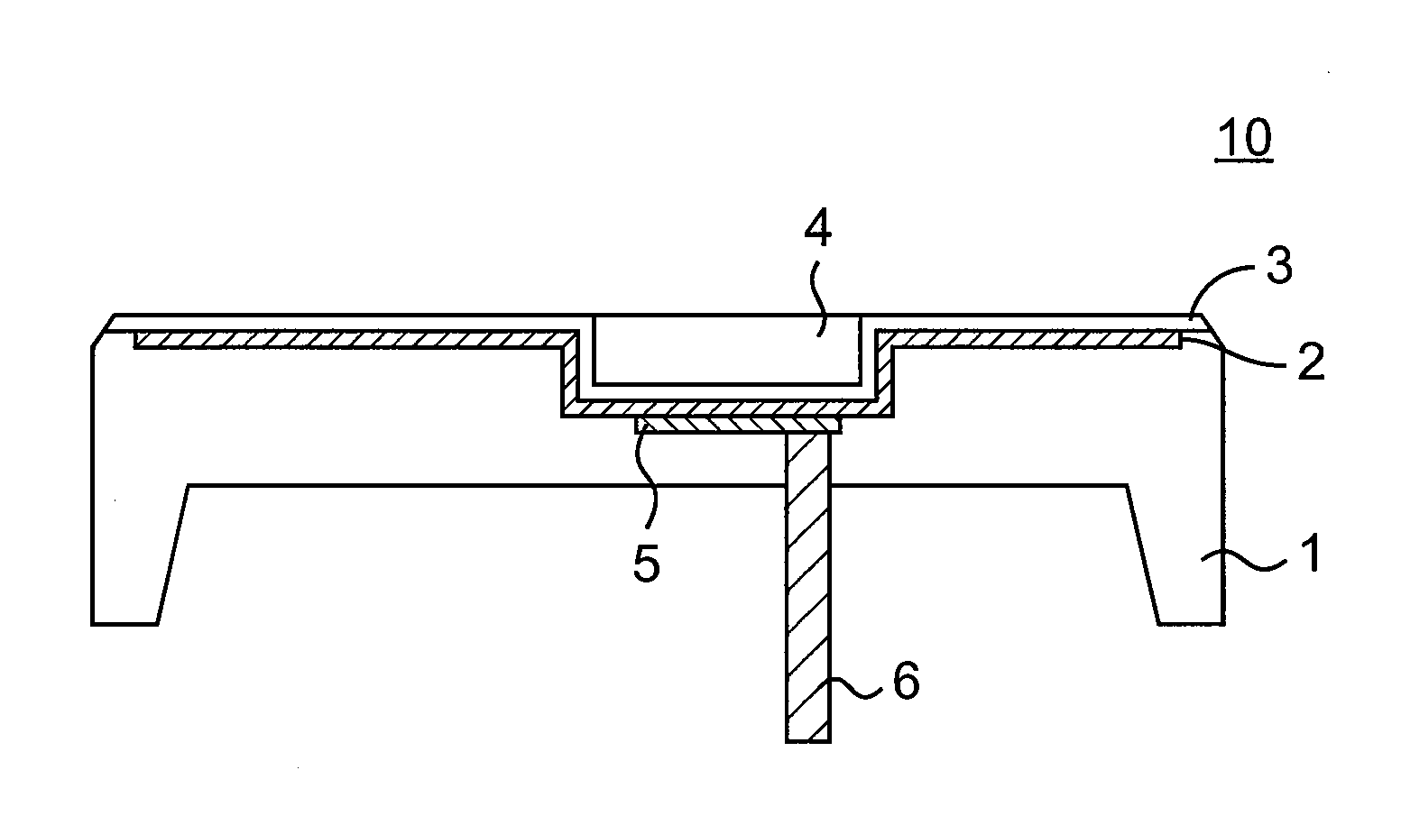
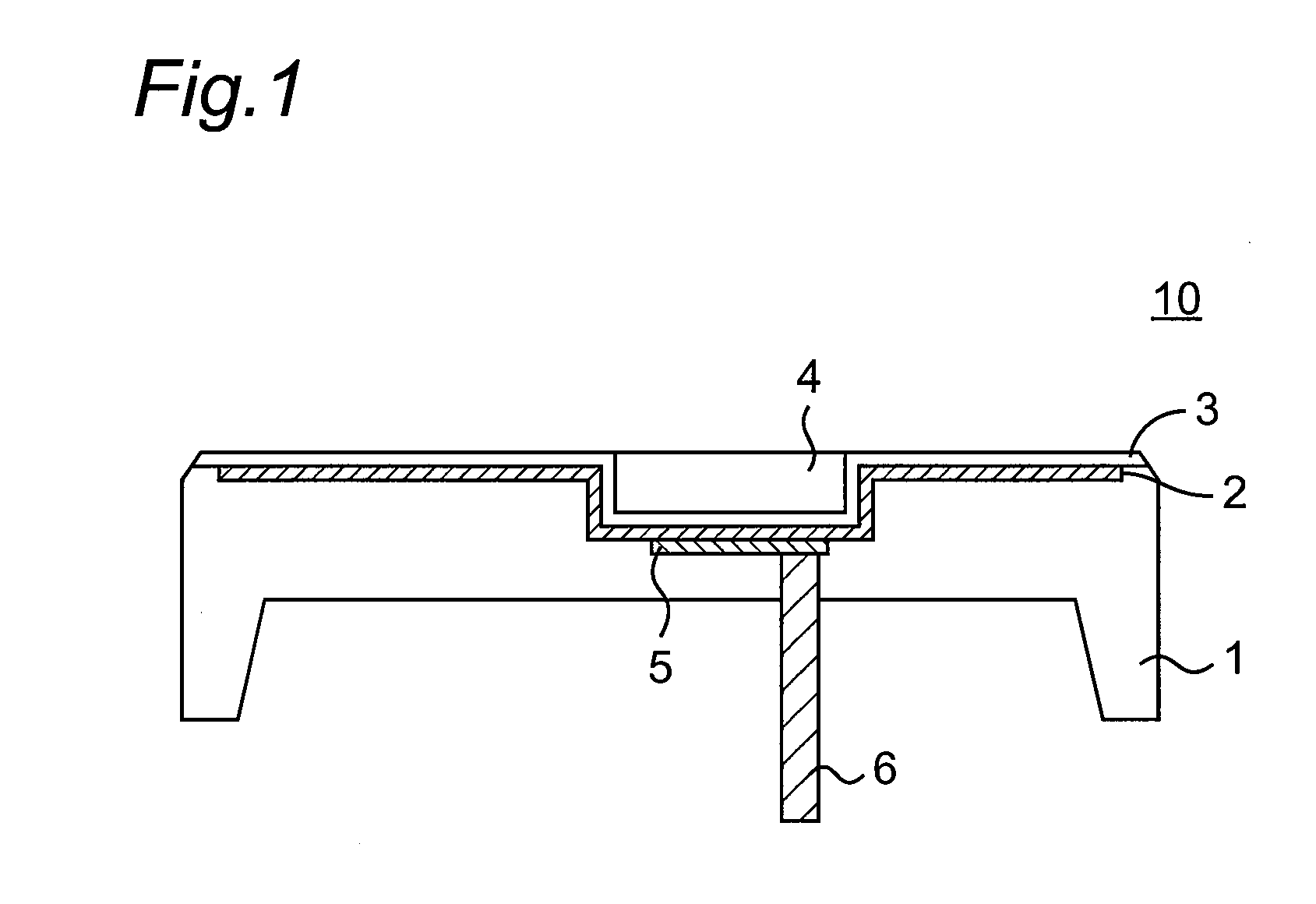
[0068]FIG. 1 is a schematic diagram showing an outline of a wireless antenna module 10 according to a first embodiment. The wireless antenna module 10 includes: a housing 1 made of a resin; a first electroconductive layer 2 provided on the front surface side of the housing 1 and functioning as an antenna; a decorative film 3 provided on the first electroconductive layer 2; a top plate 4 provided on a portion of the decorative film 3 so as to be flush with a surface of the decorative film 3; and a conduction terminal 6 provided on the back surface side of the housing 1 and electrically connected to the first electroconductive layer 2, passing through the housing 1. Note that the conduction terminal 6 is electrically connected to the first electroconductive layer 2 through a second electroconductive layer 5. Note also that the conduction terminal 6 on the back surface side of the housing 1 is provided in a position where the conduction terminal faces the top plate 4 on the front surfa...

second embodiment

[0116]FIG. 9 is a schematic cross-sectional view showing a cross-sectional configuration of a wireless antenna module according to a second embodiment. FIG. 10 is a schematic perspective view showing a connection between a pull-out portion from a first electroconductive layer 2 in FIG. 9 and a conduction terminal 6. The wireless antenna module differs from a wireless antenna module according to the first embodiment in that the conduction terminal 6 is provided as shifted from immediately below the first electroconductive layer 2 functioning as an antenna, but is provided displaced. In this case, the pull-out portion from the first electroconductive layer 2 and the conduction terminal 6 are electrically connected to each other. In addition, a top plate 4 is provided on the top surfaces of core inserts which are the conduction terminal 6 and a second electroconductive layer 5, and is disposed so as to be flush with a surface of the first electroconductive layer.

third embodiment

[0117]

[0118]A method for producing a wireless antenna module, according to a third embodiment will be described. FIGS. 11A to 11D are schematic diagrams showing the steps of a method for producing a wireless antenna module, according to the third embodiment. The method for producing a wireless antenna module differs from a method according to the first embodiment in that a conductive terminal 6 is connected to a first electroconductive layer 2 without using a crimp pin.

[0119](1) A top plate 4 which forms a part of a front surface upon molding is disposed on an inner surface of a first injection molding mold 20 for forming the front surface side upon molding. Furthermore, a decorative film 3 is disposed on the inner surface of the first injection molding mold 20 including the top plate 4. After that, a first electroconductive layer 2 is provided on the decorative film 3 (FIG. 11A). Note that for example, as shown in FIG. 3, an adhesive layer 7 for obtaining excellent adhesiveness to ...


PUM

PropertyMeasurementUnit
thicknessaaaaaaaaaa
sizeaaaaaaaaaa
thicknessaaaaaaaaaa

Abstract

A wireless antenna module includes: a housing made of a resin; an electroconductive layer provided on a front surface side of the housing; a top plate provided on a part of the electroconductive layer in a manner so as to be flush with a surface of the electroconductive layer; and a conduction terminal provided on a back surface side of the housing, and electrically connected to the electroconductive layer, passing through the housing, wherein the conduction terminal on the back surface side of the housing is provided in a position opposing the top plate on the front surface side of the housing.

Description

TECHNICAL FIELD[0001]The present invention relates to a wireless antenna module which is provided on a portable terminal to perform contactless power supply or communication, and a method for producing the wireless antenna module. More particularly, the present invention relates to an antenna module for wireless power transmission or an antenna module for wireless communication, and a method for producing the antenna module.BACKGROUND ART[0002]For charging of portable terminals such as mobile phones, personal digital assistants (PDAs), handheld game machines, and digital audio devices, normally, a contact type charging cradle that brings an electrode exposed to a housing of a portable terminal into direct contact therewith or a contactless type charging cradle where an electrode is not exposed to a surface of a housing of a portable terminal is used. At present, as a charging method for the latter contactless type charging cradle, an electromagnetic induction scheme is widely employ...

Claims


Application Information

Patent Timeline
Patent Type & Authority Applications(United States)
IPC IPC(8): H01Q1/12B29C45/14
CPCH01Q1/12B29C45/14065H01Q1/243H01Q1/40H01Q9/0407
Inventor TAKEUCHI, SHINYAYAMAZAKI, SEIICHIGOMA, SHINJIKATO, KAZUYA
Owner NISSHA PRINTING COMPANY
Why Eureka
Try Eureka