
Method for determining position of reference point

a reference point and position technology, applied in the direction of inspection/indentification of circuits, instruments, printing, etc., can solve the problems of difficult to make the position error of a reference point, the alignment mark may be altered from its predetermined shape, and the request for more severe accuracy in machining position. the effect of improving the accuracy of machining

Active Publication Date: 2009-04-21
HITACHI SEIKO LTD
View PDF2 Cites 0 Cited by
  • Summary
  • Abstract
  • Description
  • Claims
  • Application Information

AI Technical Summary

Benefits of technology

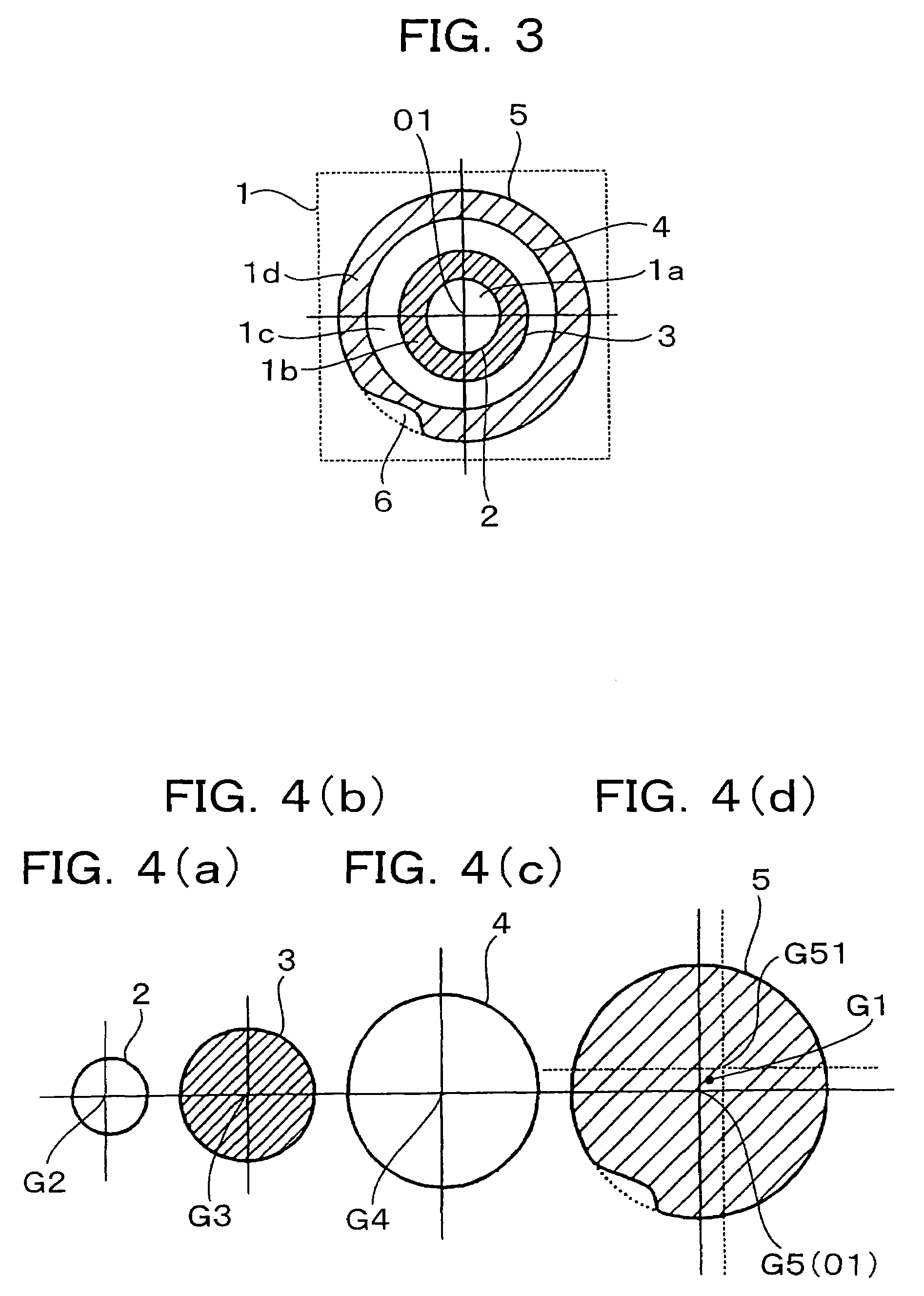
The present invention provides a method for accurately determining the position of a reference point, even when there is no influence of aberration of a camera lens or the like. This method reduces errors caused by a failure in the shape of an alignment mark. By averaging coordinate values of centers of figures surrounded by border lines of patterns and setting average values obtained in each direction as coordinate values of a reference point in machining, the accuracy of the position of each reference point can be improved. This results in improved accuracy in machining.

Problems solved by technology

However, as the holes are made smaller in diameter or smaller in pitch, more severe accuracy with respect to a machining position has been requested.
However, the alignment mark may be altered from their predetermined shape due to a failure in etching, a dust, etc.
Accordingly, due to influence of aberration of a camera lens or the like, it is difficult to make the position error of a reference point, for example, smaller than 5 μm by use of a combination of an inexpensive camera and an inexpensive camera lens.
Accordingly, due to influence of a failure in etching, a dust, etc., it is difficult to make the position error of a reference position, for example, smaller than 5 μm.

Method used


Image

  • Method for determining position of reference point
  • Method for determining position of reference point
  • Method for determining position of reference point

Examples


Embodiment Construction

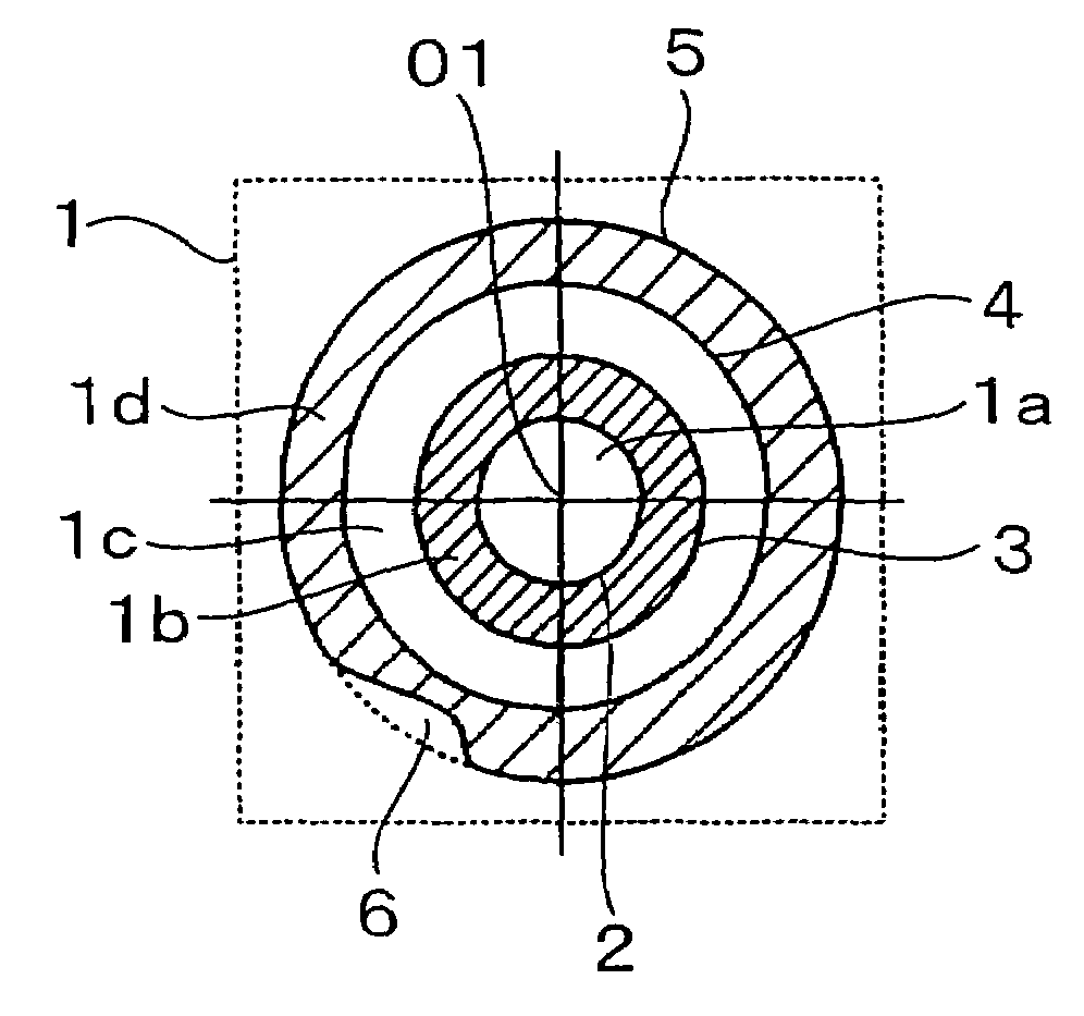
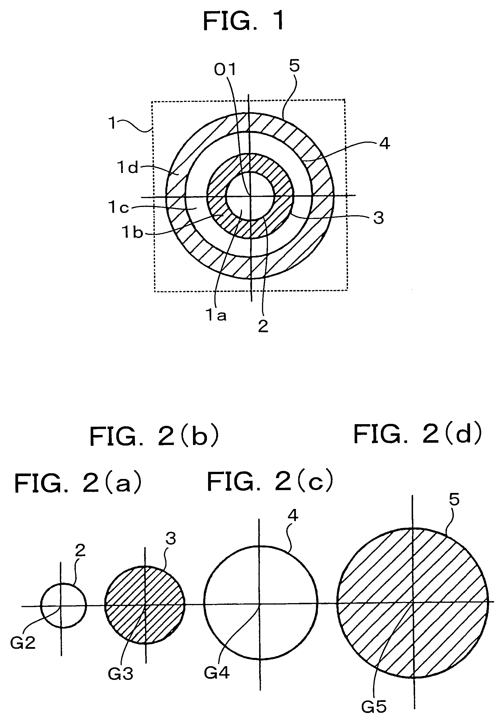
[0017]FIG. 1 is a plan view of an alignment mark according to the present invention. FIGS. 2A-2D are views for explaining a method for determining the position of a machining reference point according to the present invention.

[0018]In an alignment mark 1 enclosed by the broken line in FIG. 1, background portions 1a and 1c (white portions) and pattern portions 1b and 1d (shaded portions) of a circle pattern are formed alternately and concentrically around a designed reference point 01. The alignment mark 1 is positioned so that the reference point 01 of the alignment mark 1 is nearly aligned with the optical axis of a camera lens. After that, an image of the alignment mark 1 is picked up. When the reference point 01 of the alignment mark 1 is aligned with the optical axis of the camera lens, the influence of the aberration of the camera lens becomes the least. Accordingly, the error of a picture detection system can be reduced. Incidentally, when there is a large displacement between...


PUM


Abstract

A method for determining a position of a reference point in which there is no influence of aberration of a camera lens or the like, but an error caused by a failure in shape of an alignment mark can be reduced. An alignment mark consisting of a plurality of pattern portions (and background portions) centering at a design reference point is provided in advance. Positions of centers of border lines of the patterns are calculated. Obtained coordinate values of the centers are averaged in each axial direction. The averaged coordinate values are regarded as coordinate values of a machining reference point. Thus, even when a defect occurs in any pattern portion, an error caused by the defect is reduced so that the accuracy in machining can be improved.

Description

FIELD OF THE INVENTION[0001]The present invention relates to a method for determining a position of a reference point to be used for machining a printed circuit board or the like.BACKGROUND OF THE INVENTION[0002]As electronic equipment is reduced in size and increased in packaging density, multilayer wiring boards having a plurality of boards laminated to one another have prevailed as printed circuit boards. In any multilayer wiring board, it is necessary to electrically connect conductive layers of upper and lower laminated boards with each other. For this purpose, via holes reaching a conductive layer of a lower layer are formed in an insulating layer of the multilayer wiring board, and conductive plating is performed on the inside of each via hole so as to electrically connect the conductive layers of the upper and lower laminated boards.[0003]As via holes are made finer, a high power CO2 laser or a UV laser using harmonics of YAG is used for forming the via holes. In addition, h...

Claims


Application Information

Patent Timeline
Patent Type & Authority Patents(United States)
IPC IPC(8): G03B27/42G01B11/00H05K1/02G03B27/32H05K3/00
CPCG03B27/32H05K3/0008H05K1/0269H05K3/0026H05K2201/09781H05K2201/09918
Inventor SUGAWARA, HIROYUKIGOTO, TAKESHIKITAMURA, KOUNOSUKEAOYAMA, HIROSHI
Owner HITACHI SEIKO LTD
Learn More