Post-placement cell shifting

a post-placement and cell technology, applied in the field of post-placement cell shifting, to achieve the effect of high detailed routing cost, and high detailed routing cos

Inactive Publication Date: 2011-12-08
IBM CORP
View PDF1 Cites 0 Cited by
  • Summary
  • Abstract
  • Description
  • Claims
  • Application Information

AI Technical Summary

Benefits of technology

[0008]The present invention provides a computer implemented method, data processing system, and computer program product for reworking a plurality of cells initially placed in a circuit design. A data processing system allocates cells to tiles, wherein some tiles have single or multiple cells. The data processing system executes an expander application (or expander) to determine a high detailed routing cost tile class, wherein the high detailed routing cost tile class is a class of tiles that are expected to be difficult to complete detailed routing optimization. The expander selects a cell within a tile of the high detailed routing cost tile class to form a selected cell in a selected tile. On these cells, the expander applies multiple techniques to reposition these cells at new locations to improve the detailed routability. The expander finds a bounding box of the selected cell so that the wire length of the selected cell can be minimized. The bounding box is then expanded at four sides (north / south / east / west) to expand the placement solution space to a certain degree. Then the expander relocates the selected cell within the expanded bounding box to form a modified design with a better detailed routing cost distribution among the tiles. The expander expands the selected cell within the bounding box to form a modified design. After these transformations, the expander determines an aggregate routing cost among other steps, and affirms the modified design for further processing.

Problems solved by technology

The data processing system executes an expander application (or expander) to determine a high detailed routing cost tile class, wherein the high detailed routing cost tile class is a class of tiles that are expected to be difficult to complete detailed routing optimization.

Method used


Image

  • Post-placement cell shifting
  • Post-placement cell shifting
  • Post-placement cell shifting

Examples


Embodiment Construction

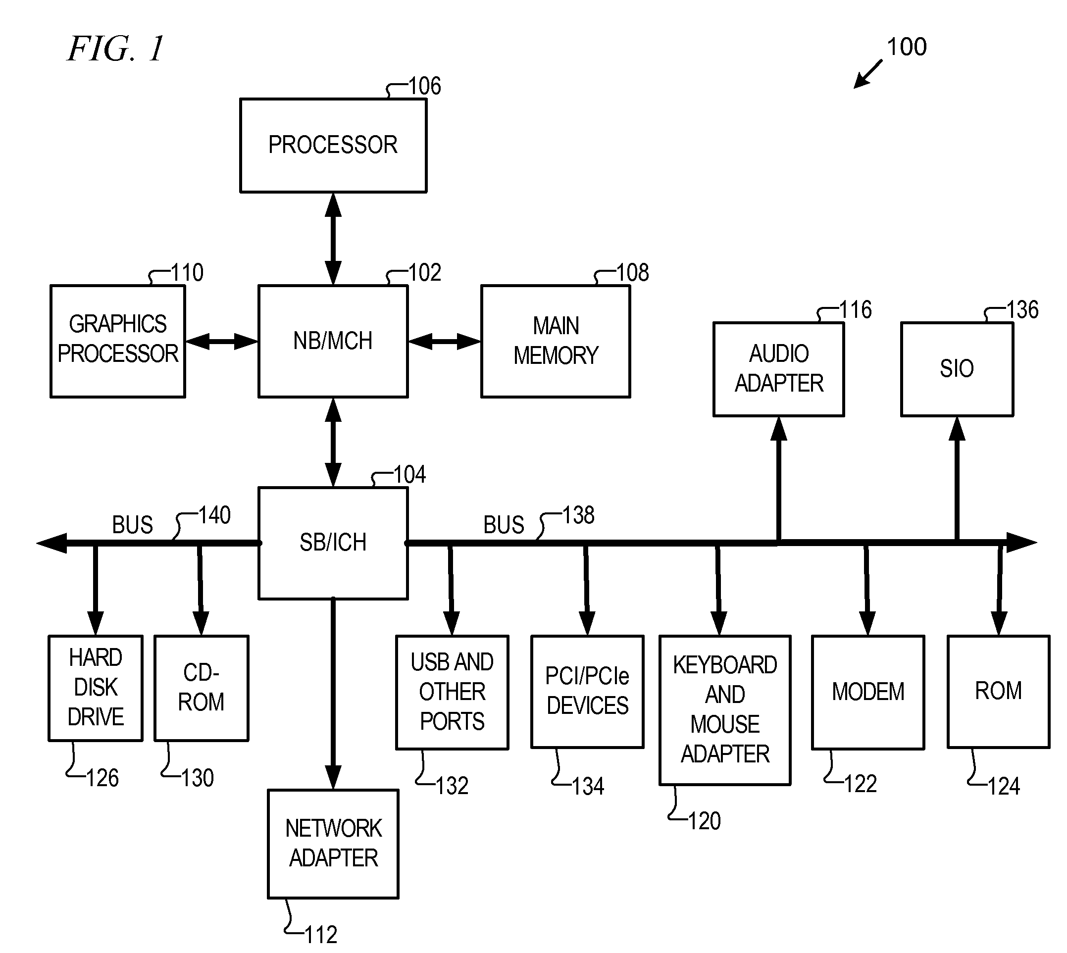
[0018]With reference now to the figures and in particular with reference to FIG. 1, a block diagram of a data processing system is shown in which aspects of an illustrative embodiment may be implemented. Data processing system 100 is an example of a computer, in which code or instructions implementing the processes of the present invention may be located. In the depicted example, data processing system 100 employs a hub architecture including a north bridge and memory controller hub (NB / MCH) 102 and a south bridge and input / output (I / O) controller hub (SB / ICH) 104. Processor 106, main memory 108, and graphics processor 110 connect to north bridge and memory controller hub 102. Graphics processor 110 may connect to the NB / MCH through an accelerated graphics port (AGP), for example.

[0019]In the depicted example, local area network (LAN) adapter 112 connects to south bridge and I / O controller hub 104 and audio adapter 116, keyboard and mouse adapter 120, modem 122, read only memory (RO...


PUM


Abstract

A computer implemented method, data processing system, and computer program product for reworking a plurality of cells initially placed in a circuit design. An expander allocates cells to tiles. The expander determines a high detailed routing cost tile class, wherein the high detailed routing cost tile class is a class of tiles that has high detailed routing costs. The expander selects a cell within a tile of the high detailed routing cost tile class to form a selected cell in a selected tile. The expander applies multiple techniques to reposition these cells at new locations to improve the detailed routability. The expander can place an expanded bounding box around the selected cell, wherein the bounding box extends to at least one tile adjacent the selected tile, and repositions the selected cell within the bounding box to form a modified design to improve the detailed routability. The expander may also inflate and legalize those cells.

Description

BACKGROUND OF THE INVENTION[0001]1. Field of the Invention[0002]The present invention relates generally to a computer implemented method, data processing system, and computer program product for electronic design automation. More specifically, the present invention relates to selecting cells and / or tiles for congestion reduction after initial placement of the library cells.[0003]2. Description of the Related Art[0004]Designing integrated circuits is a process that grows in complexity as the feature sizes of circuits shrink from one design generation to the next. As the count of circuits grows on a given die size, the number of pins or conductors that need to be routed between logical elements grows at an inverse square relationship to the size of the smallest circuit feature. Accordingly, routing, and specifically detailed routing, between and among pins has grown complex over the years. Further complexity occurs because the number of design rules that limit the allowable geometries...

Claims


Application Information

Patent Timeline
Patent Type & Authority Applications(United States)
IPC IPC(8): G06F17/50
CPCG06F17/5072G06F30/392
Inventor ALPERT, CHARLES J.LI, ZHUONAM, GI-JOONRAMJI, SHYAMREDDY, LAKSHMI N.ROY, JARROD A.TAGHAVI, TARANEHVILLARRUBIA, PAUL G.VISWANATHAN, NATARAJAN
Owner IBM CORP
Why Eureka
Try Eureka