Resin laminate manufacturing method

a manufacturing method and resin technology, applied in the direction of synthetic resin layered products, transportation and packaging, chemistry apparatus and processes, etc., can solve the problems of reduced total manufacturing efficiency, difficult to obtain difficulty in achieving resin laminates having satisfactory strength, so as to ensure manufacture efficiency and product quality, and reduce weight and wall thickness. , the effect of satisfying the

Active Publication Date: 2011-12-15
KYORAKU CO LTD
View PDF3 Cites 40 Cited by
  • Summary
  • Abstract
  • Description
  • Claims
  • Application Information

AI Technical Summary

Benefits of technology

[0012]In view of the technical problems described above, it is an object of the present invention to provide a resin laminate manufacturing

Problems solved by technology

That is, it is difficult to obtain a resin laminate having satisfactory strength with no anisotropy while ensuring manufacture efficiency.
More specifically, the first to third methods have a problem unique to extrusion molding, in common.
As the result, an extra step is required for manufacturing the resin laminate, which leads to reduction in total manufacture efficiency.
As the result, a time required for the welding is insufficient, which makes it difficult to obtain the resin laminate having satisfactory strength and degrades the quality of the resin laminate.
However, the blow molding for molding a tubular parison by application of a blowing pressure causes the following technical problem which is different from the foregoing prob

Method used


Image

  • Resin laminate manufacturing method
  • Resin laminate manufacturing method
  • Resin laminate manufacturing method

Examples


first embodiment

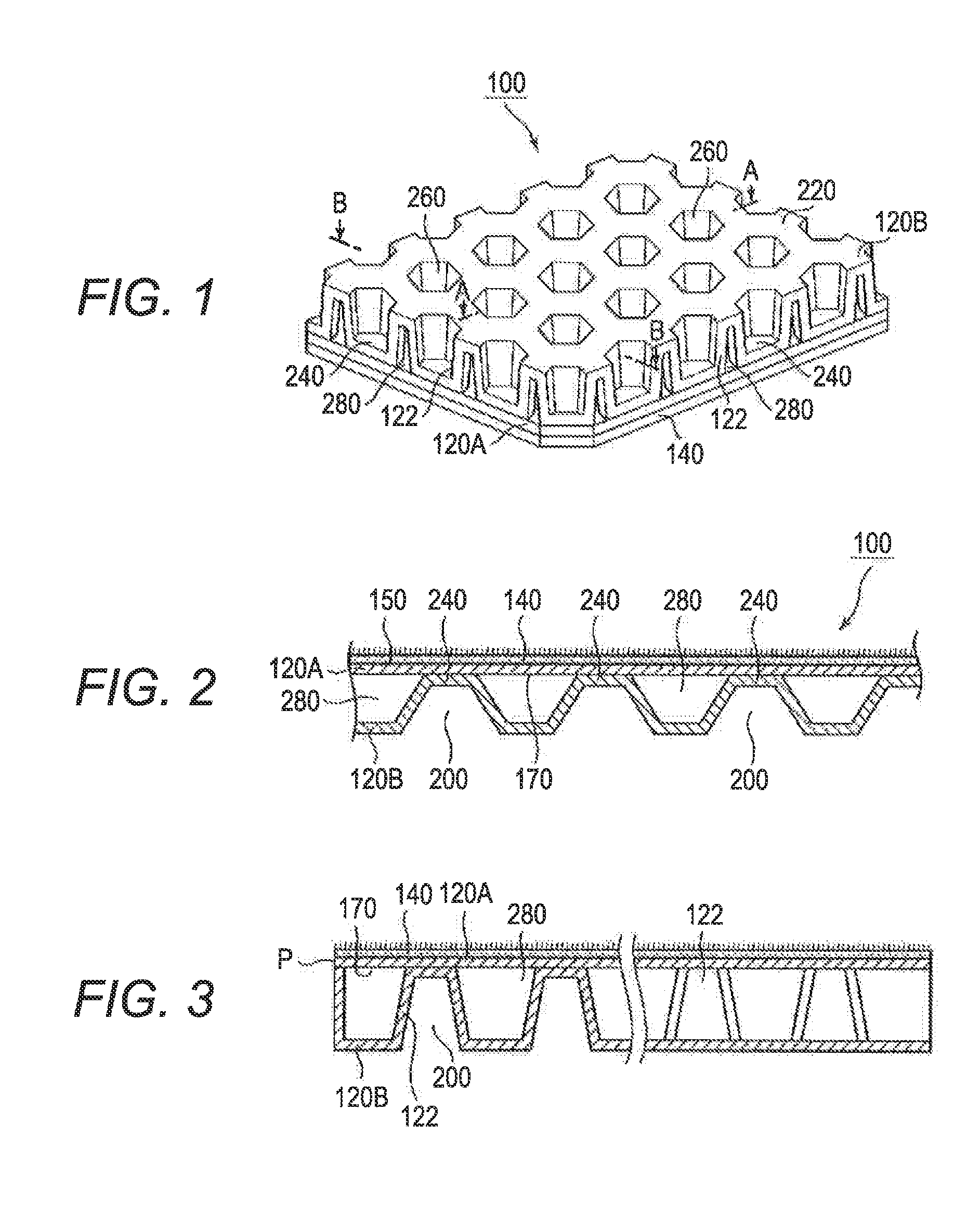
[0059]The feature of this embodiment is different from that of the first embodiment in the following point. That is, the arrangement of the cup-shaped portions 200 is devised to form a so-called fold, which is plate-like rib piece, between the adjacent cup-shaped portions 200 in the space formed by the front-side skin material sheet 120A and the back-side skin material sheet 120B. By use of this fold, the interior product is improved in lengthwise flexure stiffness. The plurality of cup-shaped portions 200 are arranged in the hermetic hollow portion 280 with a certain gap left therebetween. This gap is required for forming a fold 124, which is a plate-like rib piece and extends from the inner surface 180 of the back-side skin material sheet 120B toward the front-side skin material sheet 120A, between the adjacent cup-shaped portions 200.

[0060]The following description is given about a more specific configuration. In the first embodiment illustrated in FIG. 1, the plurality of cup-sh...

second embodiment

[0078]FIG. 12 is a view according to the present invention, which is similar to FIG. 1.

[0079]FIG. 13 is a view according to the second embodiment of the present invention, which is similar to FIG. 3.

[0080]FIG. 14 is a sectional view taken along line C-C in FIG. 8, which illustrates a fold.

[0081]FIG. 15 is a view according to the second embodiment of the present invention, which is similar to FIG. 2.


PUM

PropertyMeasurementUnit
Weightaaaaaaaaaa
Thicknessaaaaaaaaaa
Pressureaaaaaaaaaa

Abstract

An object is to provide a method for manufacturing a resin laminate IOU, the method being capable of achieving satisfactory reduction in weight and wall thickness while ensuring manufacture efficiency and product quality. To accomplish the object, a resin laminate manufacturing method includes a step of providing a pair of split mold blocks one of which has a cavity provided with a plurality of protrusions each extending toward the other one, and preparing two molten thermoplastic resin sheets each having a thickness adjusted, a step of feeding the two molten thermoplastic resin sheets between the pair of split mold blocks with a predetermined gap left therebetween such that each thermoplastic resin sheet protrudes around annular pinch-off parts, a step of forming a hermetic space between one of the sheets and the cavity of the one mold block opposed to an outer surface of the one sheet, a step of sucking air in the hermetic space from the one mold block side, pressing the outer surface of the one sheet against the cavity of the one mold block to shape the one sheet, and forming cup-shaped portions, and a step of clamping the pair of mold blocks, welding peripheral edges of the two molten thermoplastic resin sheets to each other, and welding the bottoms of the cup-shaped portions formed on the one sheet to an inner surface of the other sheet. According to this method, in the resin laminate thus manufactured, the two sheets are substantially equal in thickness to each other.

Description

RELATED APPLICATIONS[0001]The present application is a National Phase of International Application Number PCT / JP2011 / 050018, filed Feb. 9, 2011, which claims priority from, Japanese Application Number 2009-299038, filed Dec. 29, 2009, and Japanese Application Number 2009-299074, filed Dec. 29, 2009.TECHNICAL FIELD[0002]The present invention relates to resin laminate manufacturing methods. More specifically, the invention relates to a resin laminate manufacturing method capable of achieving satisfactory reduction in weight and wall thickness while ensuring manufacture efficiency and product quality.BACKGROUND ART[0003]Heretofore, so-called resin laminates have been adopted as interior components for automobiles, components for building, and packaging components for physical distribution. A resin laminate includes a front-side member made of resin and a back-side member made of resin. The back-side member is provided with a cup-shaped portion the bottom of which butts against an inner...

Claims


Application Information

Patent Timeline
IPC IPC(8): B29C70/40B29C48/475
CPCB29C47/0019B29C47/366B29C51/10B29C51/267B29C2791/006B29C2947/9258B29C2947/926B32B3/28B32B27/08B32B27/12B32B27/32B32B2250/03B32B2262/0253B32B2262/0276B60R13/013B29C49/4802B29C51/02B29C51/36B29C2049/0057B29C2049/023B29C49/041B29C2049/047B29C2049/048B29C2049/2017B29C2049/203B29C2049/4807B29C2049/4812B29C47/54B32B27/18B32B27/302B32B3/12B32B2262/0223B32B2262/0246B32B2262/0261B32B2262/0292B32B2262/04B32B2262/062B32B2262/065B32B2262/101B32B2262/106B32B2262/14B32B2264/104B32B2274/00B32B2307/702B32B2307/732B32B7/05B29C48/07B29C48/385B29C48/475B29C2948/926B29C2948/9258B29C49/06914B29C49/04108B29C49/04104B29C49/4812B29C49/04B29C49/58B32B3/30B60R13/01B29C70/40
Inventor SUMI, TAKEHIKOMATSUBARA, YOSHITAKA
Owner KYORAKU CO LTD
Why Eureka
Try Eureka