Optical Fiber Illumination Systems and Methods

a technology of optical fibers and illumination systems, applied in the direction of fibre light guides, lighting and heating apparatus, instruments, etc., can solve the problem that optical fibers are not considered to be well-suited for use in forming extended illumination sources

Active Publication Date: 2011-12-15
CORNING INC
View PDF22 Cites 62 Cited by
  • Summary
  • Abstract
  • Description
  • Claims
  • Application Information

AI Technical Summary

Benefits of technology

[0013]Thus, one advantageous feature of at least some embodiments of the present invention is that the illumination systems and methods that utilise the optical fibers' ability to efficiently deliver light to remote locations and that such fibers will scatter light relatively uniformly even when deployed in different shapes (e.g., bent, coiled or straight) to match the needs of application. In addition, one advantageous feature of some embodiments of the present invention is that the light diffusing fibers according to at least some of the exemplary embodiments of the present invention are capable of providing illumination with a weak wavelength dependence, wherein the scattering loss LS within the 200 nm to 2000 nm wavelength range is proportional to λ−p, where p is greater or equal to 0 and less than 2, preferably less than 1, and more preferably less than 0.5 or even more preferably less than 0.3. Another advantageous feature of at least some embodiments of the present invention is the capability of having substantially uniform scattering along the length (e.g., less than 50% and more preferably less than 30% variation from the maximum), and in angular space away from the axis of the fiber, such that forward, 90 degrees (from axis of the fiber) and backward scattering intensities are almost the same (e.g., within 30% of each other, and preferably within 20% of each other).
[0016]One advantageous feature of the fibers according to some embodiments of the present invention and of the illumination system utilising such fibers, is that the fiber acts as a light source, and illuminates the desired medium by uniformly scattering light through the sides of the fiber rather than delivering an intense and localized beam of light from the end of the fiber. Furthermore, in some embodiments, the use of fiber advantageously allows the electrically driven light source to remain distant from the point(s) of light delivery. This fact would be most beneficial in aqueous or potentially explosive environments where the electrical components could be located a safe distance from the conductive or reactive environment.

Problems solved by technology

Because optical fibers are typically designed to efficiently deliver light from one end of the fiber to the other end of the fiber over long distances, very little light escapes from the sides of the typical fiber, and, therefore optical fibers are not considered to be well-suited for use in forming an extended illumination source.

Method used

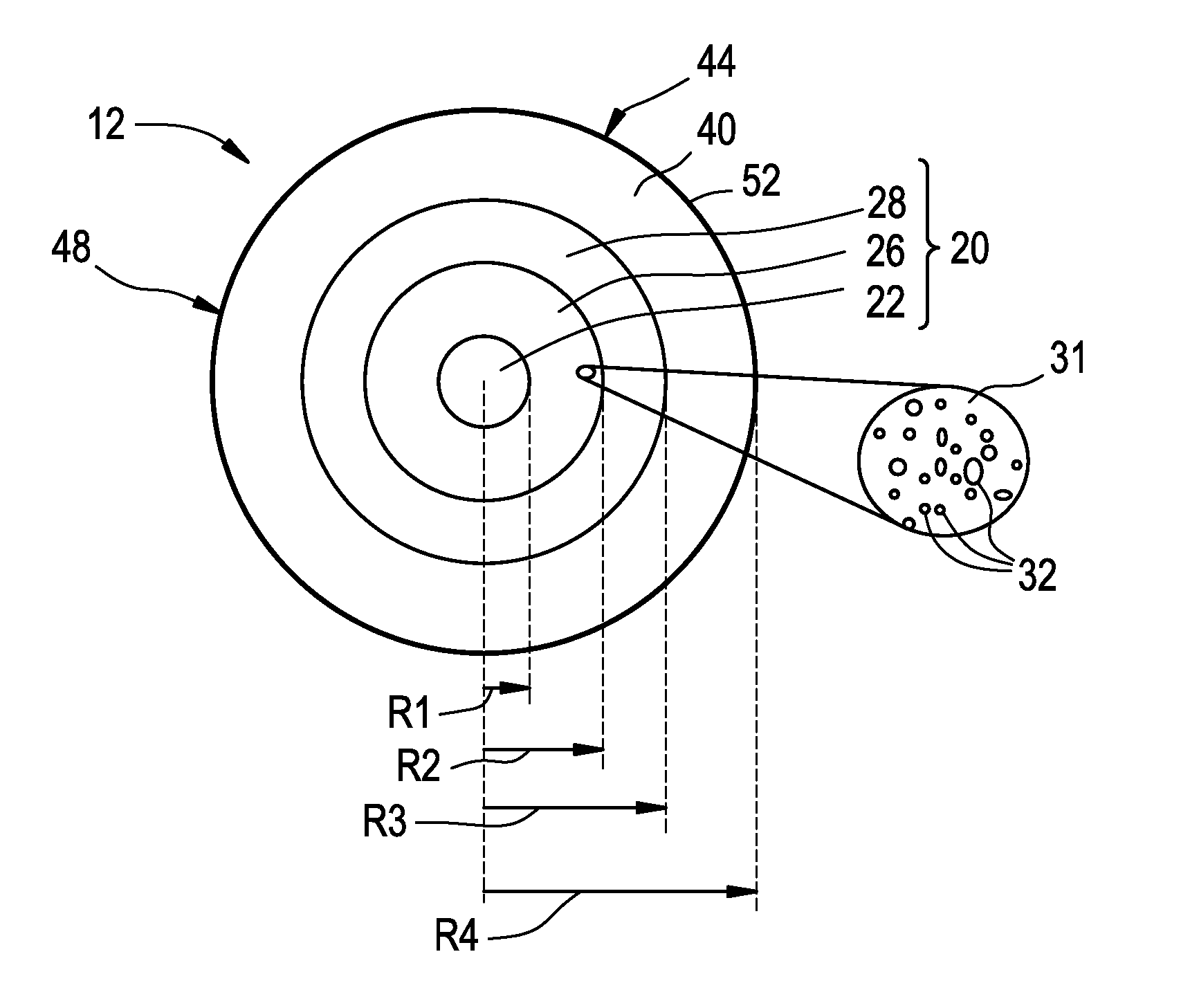
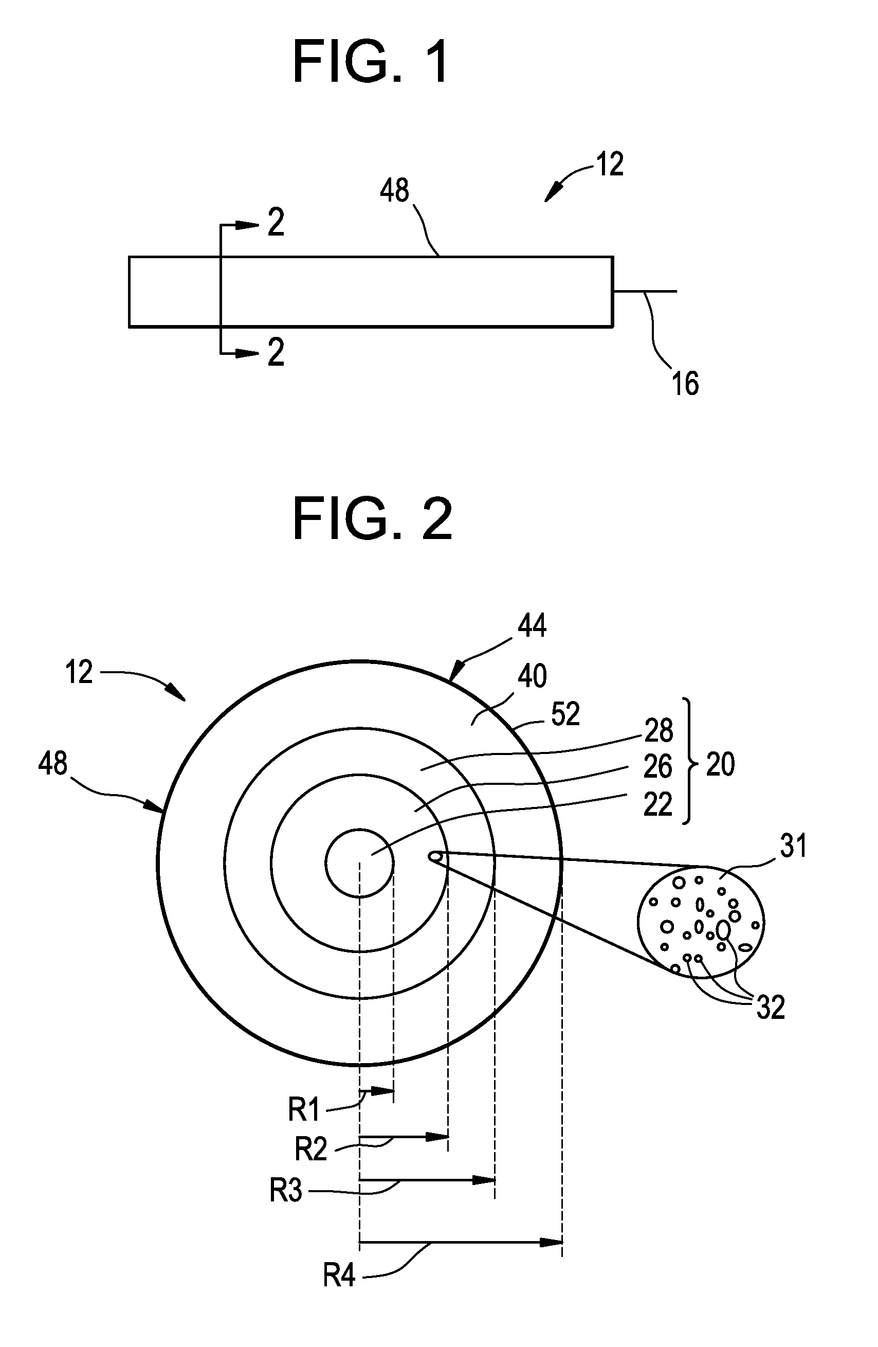
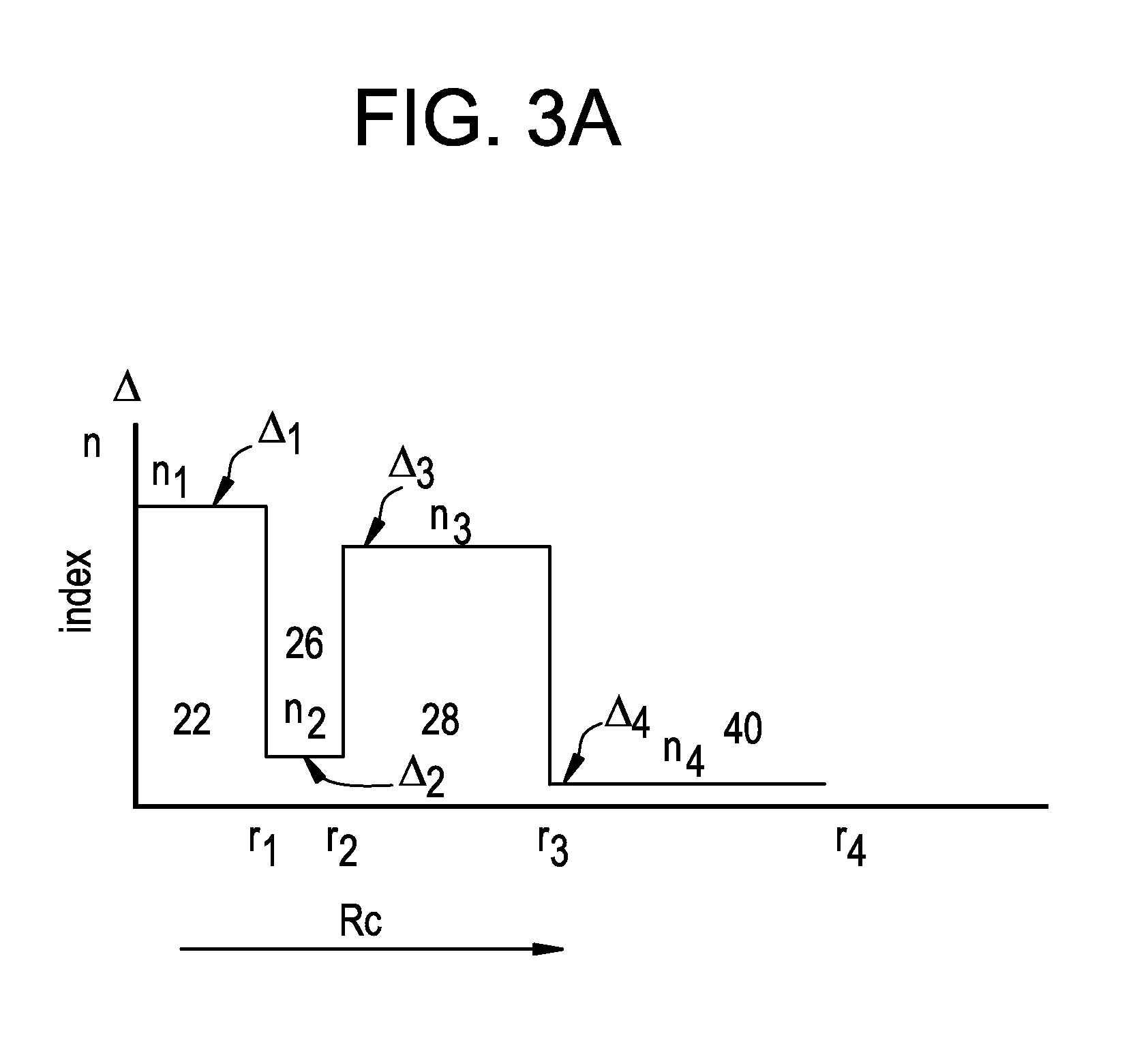

Image

  • Optical Fiber Illumination Systems and Methods
  • Optical Fiber Illumination Systems and Methods
  • Optical Fiber Illumination Systems and Methods

Examples


Embodiment Construction

[0031]Reference is now made in detail to the present preferred embodiments of the invention, examples of which are illustrated in the accompanying drawings. Whenever possible, like or similar reference numerals are used throughout the drawings to refer to like or similar parts. It should be understood that the embodiments disclosed herein are merely examples, each incorporating certain benefits of the present invention.

[0032]Various modifications and alterations may be made to the following examples within the scope of the present invention, and aspects of the different examples may be mixed in different ways to achieve yet further examples. Accordingly, the true scope of the invention is to be understood from the entirety of the present disclosure, in view of but not limited to the embodiments described herein.

Definitions

[0033]Terms such as “horizontal,”“vertical,”“front,”“back,” etc., and the use of Cartesian Coordinates are for the sake of reference in the drawings and for ease o...


PUM

PropertyMeasurementUnit
core diameteraaaaaaaaaa
diameteraaaaaaaaaa

Abstract

An illumination system generating light having at least one wavelength within 200 nm a plurality of nano-sized structures (e.g., voids). The optical fiber coupled to the light source. The light diffusing optical fiber has a core and a cladding. The plurality of nano-sized structures is situated either within said core or at a core-cladding boundary. The optical fiber also includes an outer surface. The optical fiber is configured to scatter guided light via the nano-sized structures away from the core and through the outer surface, to form a light-source fiber portion having a length that emits substantially uniform radiation over its length, said fiber having a scattering-induced attenuation greater than 50 dB / km for the wavelength(s) within 200 nm to 2000 nm range.

Description

[0001]This application is a continuation of U.S. patent application Ser. No. 12 / 950,045 filed on Nov. 19, 2010 entitled “Optical Fiber Illumination Systems and Methods” claims the benefit of priority under 35 USC 119(e) of U.S. Provisional Application Ser. No. 61 / 263,023 filed Nov. 20, 2009.BACKGROUND[0002]1. Field[0003]The present invention relates generally to light diffusing optical fibers having a region with nano-sized structures, and in particular to illumination systems and methods that employ such fibers for different applications including bioreactors, signage and special lighting applications.[0004]2. Technical Background[0005]Optical fibers are used for a variety of applications where light needs to be delivered from a light source to a remote location. Optical telecommunication systems, for example, rely on a network of optical fibers to transmit light from a service provider to system end-users.[0006]Telecommunication optical fibers are designed to operate at near-infra...

Claims


Application Information

Patent Timeline
Patent Type & Authority Applications(United States)
IPC IPC(8): G02B5/02G02B6/44
CPCG02B6/0003G02B6/001G02B6/02347C03C25/1045G02B6/02366C03C13/045C03C25/102G02B6/02361C03B37/018C03B37/025C03C25/105C03C25/106C03C25/475G02B6/0229
Inventor BICKHAM, SCOTT ROBERTSONBOOKBINDER, DANA CRAIGFEWKES, EDWARD JOHNLOGUNOV, STEPHAN LVOVICH
Owner CORNING INC
Why Eureka
Try Eureka