Eureka AIR delivers breakthrough ideas for toughest innovation challenges, trusted by R&D personnel around the world.

Pet Vacuum Cleaner

Inactive Publication Date: 2011-12-22
CASPER ROBERT W
View PDF4 Cites 27 Cited by
  • Summary
  • Abstract
  • Description
  • Claims
  • Application Information

AI Technical Summary

Benefits of technology

[0014]It is an object of the present invention to provide a cleaning device that effectively dislodges hair and debris for collection by a vacuum system.
[0015]It is a further object of the present invention to provide a cleaning device that will not cause pain or irritation to the pet.
[0016]It is yet a further object of the present invention to provide a cleaning device that is easy to clean and prepare for additional uses.
[0017]It is still a further object of the present invention to provide a cleaning device that is efficiently designed so as to maximize the capabilities of a low-power and low-torque electric motor.
[0018]It is yet a further object of the present invention to provide a cleaning device that is hand-held and easy to use.

Problems solved by technology

Shed pet hair is generally perceived as unhygienic and may reflect poorly on a pet owner's cleanliness in the eyes of their colleagues.
Pet hair also can cause or exacerbate allergic reactions in pet owners or those that visit their homes.
As many pet owners can attest, this can be a time consuming chore, and one that must be repeated on a weekly or bi-weekly basis.
Many difficulties have been encountered in designing such devices to effectively handle the substantial quantity of hair generated by the pet.
Unfortunately, it has been found that the devices of the prior art intended to aid pet owners in grooming and cleaning their pets have significant shortcomings.
For instance, it is often the case that brush or comb teeth or bristles do not provide sufficient loosening of a pet's hair.
The result is that the user must repeatedly clean the teeth or bristles.
The teeth or bristles also often cause pain or irritation to the pet.
It has also been found that many devices are inconvenient to clean.
The use of a collection bag significantly complicates the cleaning of the device, as many parts must be opened or disassembled in order to prepare the device for an additional use after the collection bag is filled.
It has further been found that the devices of the prior art are designed such that the vacuum means are relatively weak and / or require frequent replacement of batteries.
Pets are often fearful of loud noises, and many vacuum systems are relatively loud.
Vacuum systems with such motors have been known to perform poorly due to inefficiencies in the design of the vacuum system.

Method used


Image

  • Pet Vacuum Cleaner
  • Pet Vacuum Cleaner
  • Pet Vacuum Cleaner

Examples


Embodiment Construction

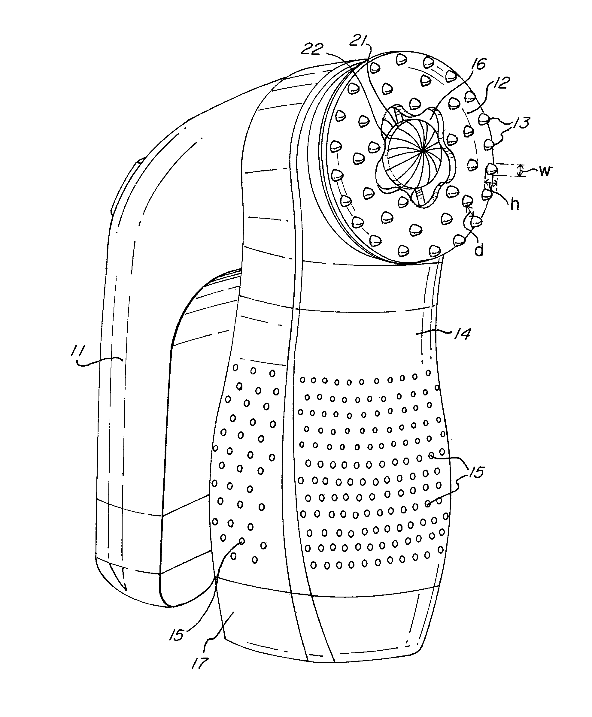
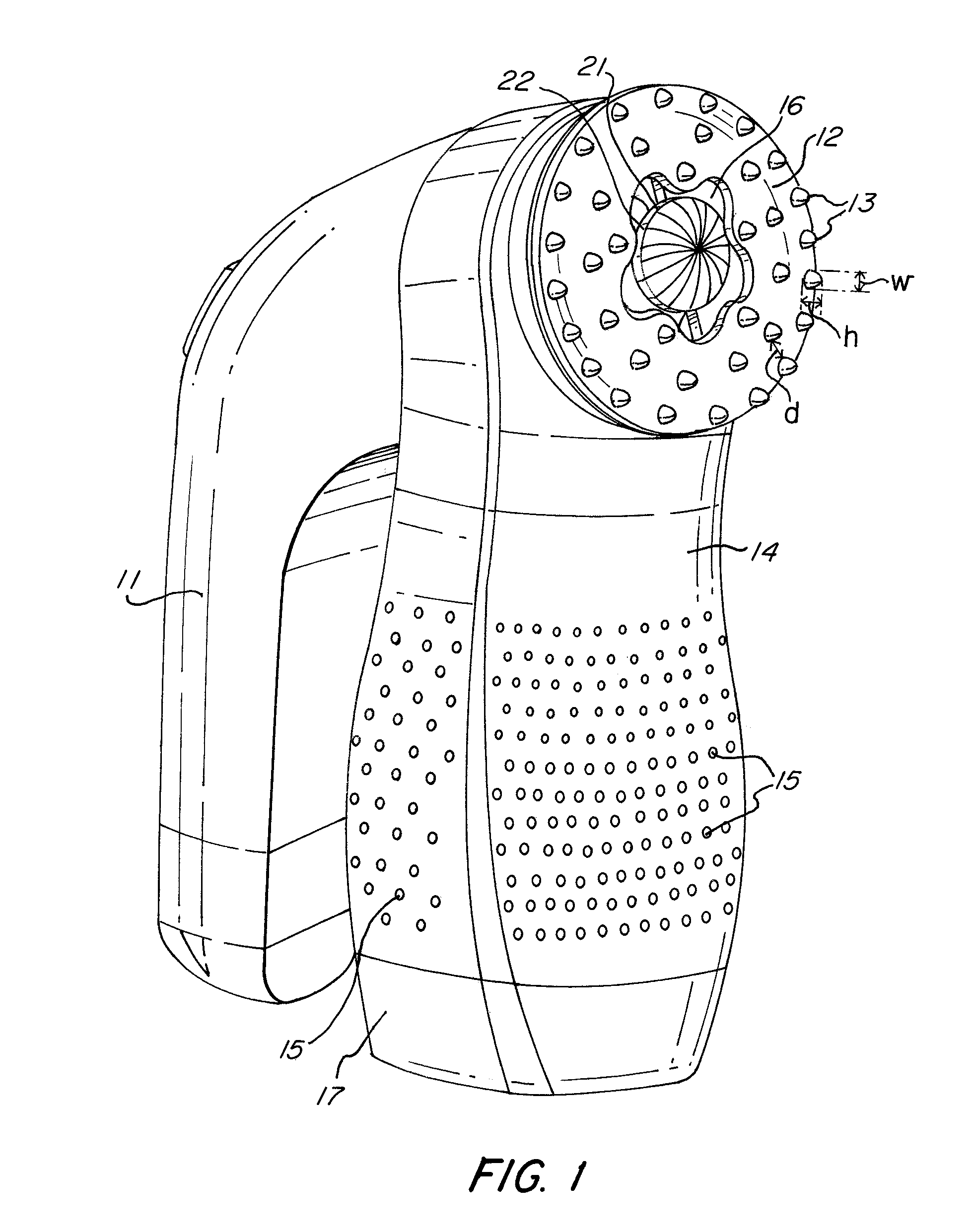
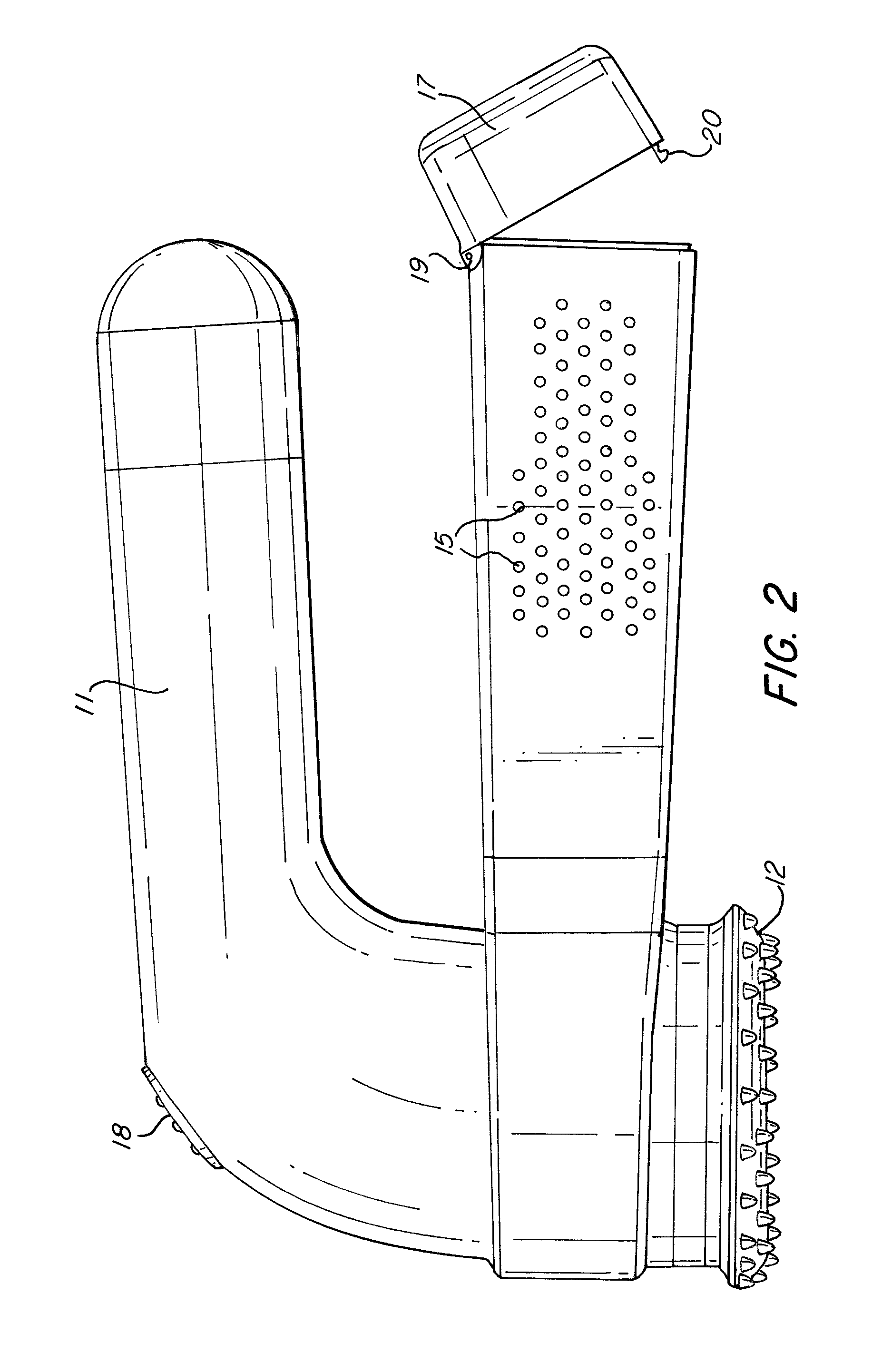
[0039]Embodiments of the present invention will now be described with reference to the attached drawings. FIG. 1 shows a first exemplary embodiment of a cleaning device according to the present invention. The cleaning device 10 is hand-held, and includes a handle 11 for grasping by a single hand of a user. The device 10 also has a contact head 12, which includes a plurality of protrusions 13. Below the contact head 12 in FIG. 1 is a collection container 14. The collection container 14 has a plurality of holes 15.

[0040]The contact head 12 has an opening 16 at or near its center. Through opening 16, the disk portion 22 of the impeller 21 can be seen. The impeller 21 will be described in more detail below. The impeller 21 is driven by a motor so that it rotates and creates a vacuum. The internal parts of device 10 are shown in FIG. 3, which is a cross-sectional view and is described below.

[0041]The contact head 12 is intended to contact the surface to be cleaned by the device, for exam...


PUM


Abstract

A hand-held cleaning device that utilizes a low-power, low-torque motor coupled to an impeller for creating a vacuum. The device includes a contact head having a plurality of protrusions formed on its top surface. The contact head contacts the surface to be cleaned, for example, the coat of a pet. The protrusions are sized and spaced to avoid tangling or clumping of pet hair. The device includes a container for collecting hair and debris. The impeller includes ribs on a disk portion thereof for increasing the efficiency of the vacuum system.

Description

CROSS-REFERENCE TO RELATED APPLICATIONS[0001]This application is a continuation-in-part of pending International Application No. PCT / US2010 / 021357, filed Jan. 19, 2010, and also is a continuation-in-part of pending U.S. application Ser. No. 12 / 355,352, filed Jan. 16, 2009. The contents of both of those applications are incorporated herein by reference.FIELD OF THE INVENTION[0002]The present invention relates to a cleaning device. Specifically, the present invention relates to a hand-held cleaning device that is advantageously used on pets and other animals.BACKGROUND OF THE INVENTION[0003]Pet ownership is widespread in most parts of the world, and many pet owners spend a considerable amount of time grooming and cleaning up after their pets. For example, many “short-hair” pets are prone to “shedding.” This is the term for the normal and systematic loss of hair by the animal. For some animals, a large volume of hair is shed at certain times during the year, while some animals seem to ...

Claims


Application Information

Patent Timeline
IPC IPC(8): A47L5/24
CPCA01K13/001A01K13/002A47L5/24A47L7/00A47L9/1409A47L9/149A47L9/1683B26B19/44A47L9/0613
Inventor CASPER, ROBERT W.
Owner CASPER ROBERT W
Why Eureka
Eureka Blog
Learn More