

Laser spark plug and prechamber module for same
a laser and prechamber technology, applied in the field of laser spark plugs, can solve the problems of not being economical, replacing the entire laser spark plug with the integrated prechamber, etc., and achieve the effect of avoiding the disadvantages of conventional systems and flexible us
- Summary
- Abstract
- Description
- Claims
- Application Information
AI Technical Summary
Benefits of technology
Problems solved by technology
Method used
Image

Examples
Embodiment Construction
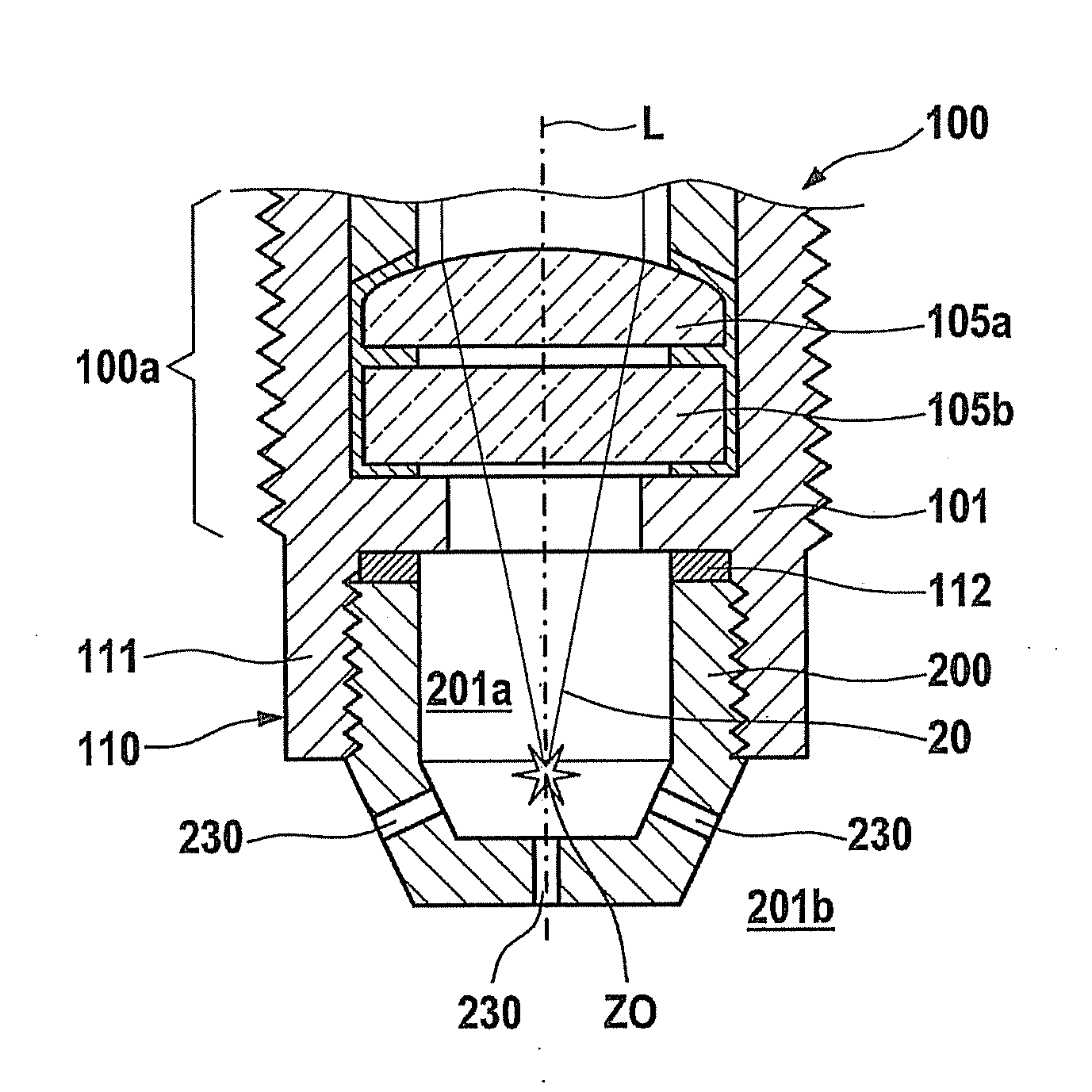
[0030]FIG. 1 shows a partial cross section of a laser spark plug 100 according to the present invention, of which generally only end region 100a thereof facing the combustion chamber is illustrated. Laser spark plug 100 is screwed into a cylinder head of an internal combustion engine in a conventional manner.
[0031]Laser spark plug 100 has a laser device, not illustrated, which provides high-energy laser pulses 20, which are focused on an ignition site ZO via a focusing lens 105a and are uncoupled from laser spark plug 100 via a combustion chamber window 105b in the optical path downstream from focusing lens 105a.
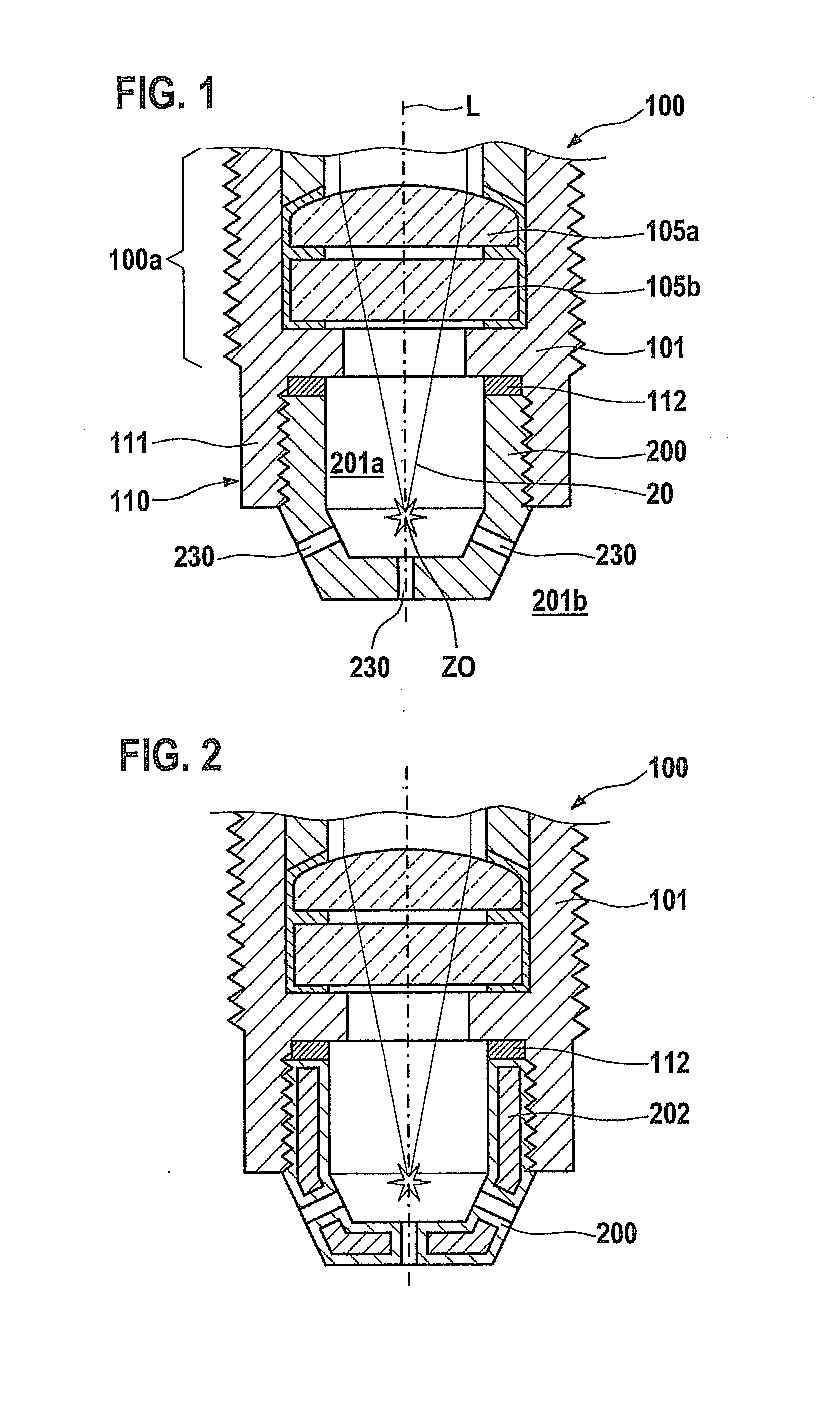
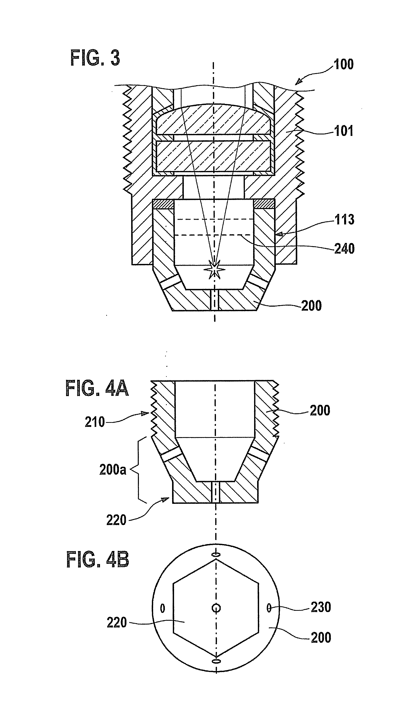
[0032]To implement a prechamber system, laser spark plug 100 according to the present invention has a prechamber module 200, illustrated in FIG. 1. In contrast to conventional laser spark plugs having a prechamber system, prechamber module 200 is designed as a separate component, and it is thus possible to connect the prechamber module to laser spark plug 100 after the lase...
PUM
 Abstract
Description
Claims
Application Information