Motor

a technology of motors and rotors, applied in the direction of rotating magnets, magnetic circuit rotating parts, synchronous machines with stationary armatures, etc., can solve the problems of easy occurrence of magnetic imbalance, deterioration of rotational performance, increase in vibration, etc., to reduce vibration and improve rotational performance.

Active Publication Date: 2011-12-22
DENSO CORP
View PDF3 Cites 33 Cited by
  • Summary
  • Abstract
  • Description
  • Claims
  • Application Information

AI Technical Summary

Benefits of technology

[0005]It is an objective of the present invention to provide a motor that reduces vibration and can improve rotational performance.

Problems solved by technology

For this reason, a magnetic imbalance easily occurs.
This leads to deterioration of rotational performance such as an increase in vibration caused by, for example, generation of cogging torque.

Method used


Image

  • Motor
  • Motor
  • Motor

Examples


first embodiment

[0053]A first embodiment obtained by embodying the present invention will be described below with reference to the accompanying drawings.

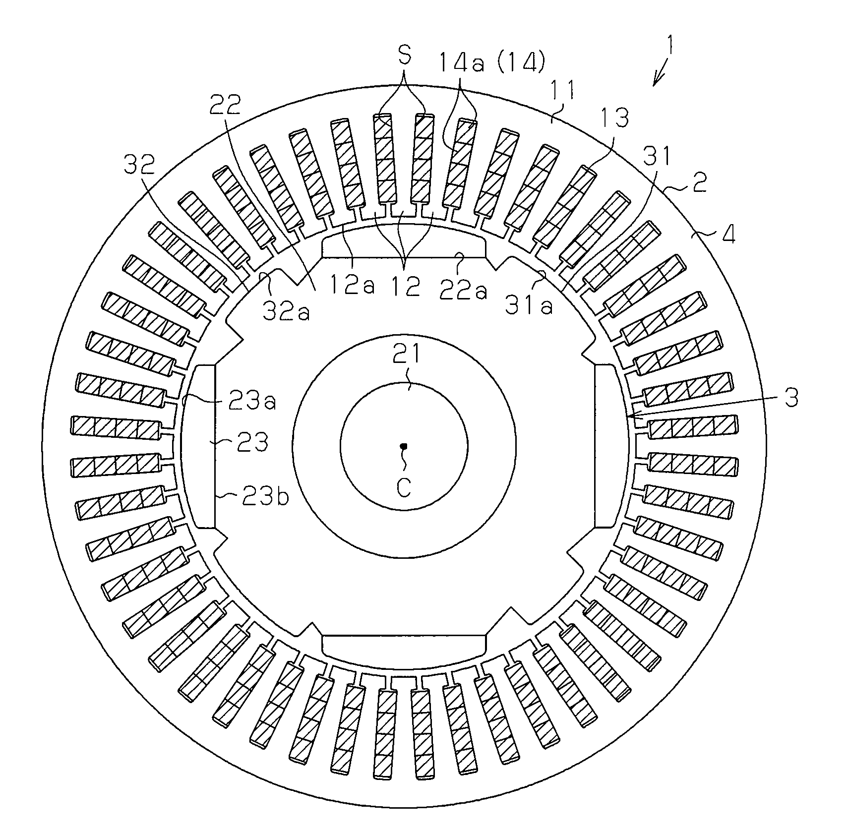
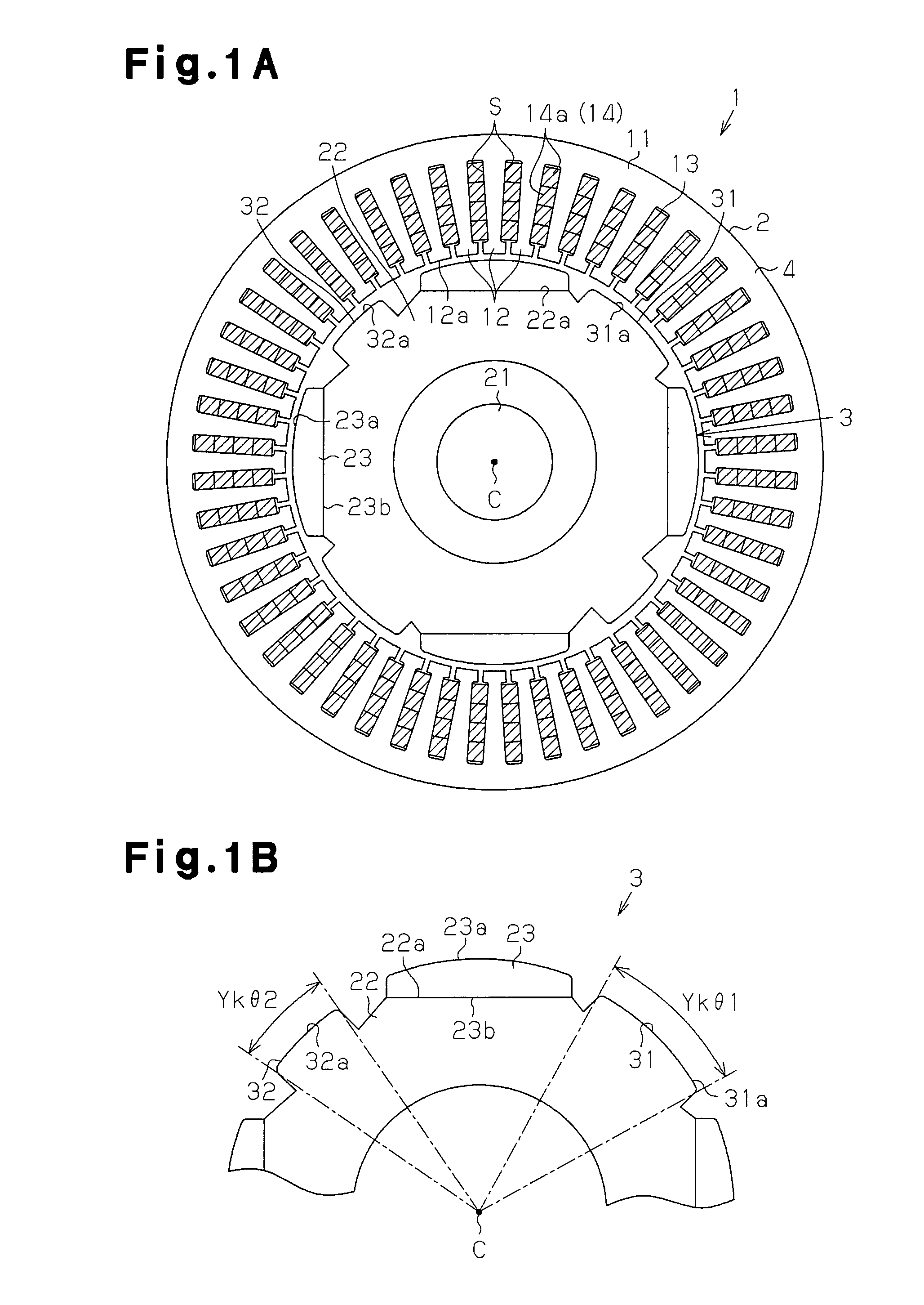
[0054]As shown in FIG. 1A, an inner-rotor type motor 1 includes a substantially annular stator 2 and a rotor 3 arranged inside the stator 2 in the radial direction thereof. The stator 2 substantially encloses the rotor 3.

[0055]The stator 2, as shown in FIGS. 1A and 1B, includes a stator core 4. The stator core 4 has a cylindrical portion 11 and a plurality of (in the present embodiment, forty-eight) teeth 12 extending from the cylindrical portion 11 to the inside in the radial direction and arranged at equal intervals in the circumferential direction. Slots S are formed between adjacent teeth 12. Segment coils 13 for generating magnetic fields that rotate the rotor 3 are inserted into the slots S. More specifically, the number of slots S is equal to the number of the teeth 12 (in the present embodiment, forty-eight). Insulators (not shown) are inte...

second embodiment

[0091] the following advantages can be obtained.

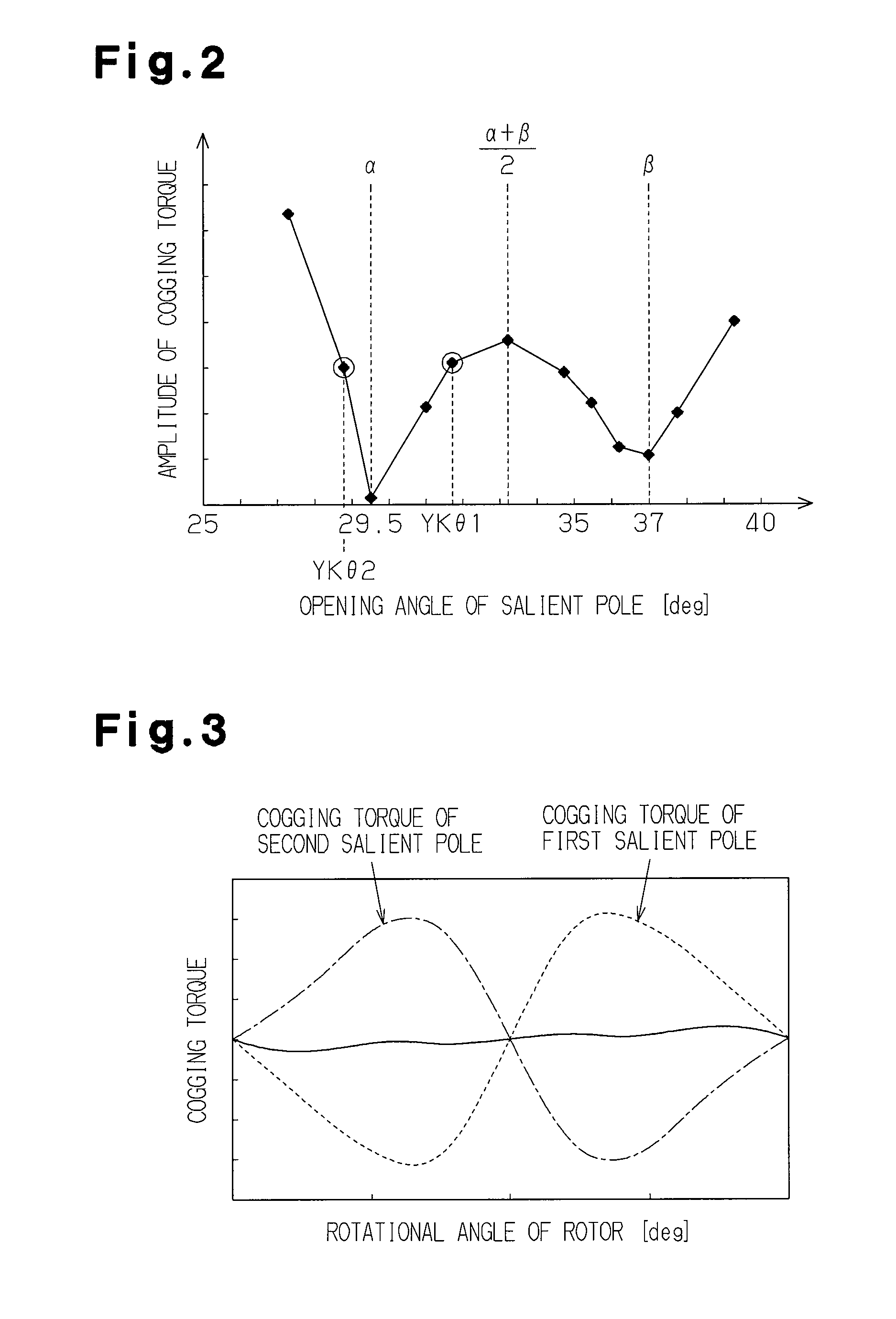
[0092](4) In the present embodiment, the opening angle of the outer surface 124a of the salient pole 124 is defined as an opening angle Ykθ(°), the opening angle between both the circumferential ends of the distal end portion 12a of one of the teeth 12 is defined as a opening angle Tθ(°), and the total number of teeth 12 arranged on the cylindrical portion 11 is represented by L. In this case, the opening angle Ykθ is set to satisfy the above expression (4). For this reason, when one end portion 124b in the circumferential direction of the outer surface 124a of the salient poles 124 overlaps one end portion 12x in the circumferential direction of the distal end portion 12a of the arbitrary first tooth 12 (tooth 12b) in the radial direction, the other end portion 124c in the circumferential direction of the outer surface 124a overlaps the other end portion 12y in the circumferential direction of the “a”th tooth 12 (tooth 12c) from the f...

third embodiment

[0103] the following advantages can be obtained.

[0104](1) In the motor 201 having fourteen magnetic poles and twelve slots, the ratio A / B of the circumferential width A of the magnet 223 and the circumferential width B at a distal end (tooth distal end portion 212a) of the tooth 212 is set to satisfy the expression 0.85203 becomes small (for example, smaller than that obtained when A / B=1) (see an experiment result in FIG. 17), and consequently, vibration can be reduced. More specifically, FIG. 17 shows the magnitude of the unbalanced load generated on the rotor 203 when the ratio A / B was changed in the experiment. As is apparent from FIG. 17, when the ratio A / B satisfies the expression 0.85223 is simply set to be equal to the circumferential width B at the distal end (tooth distal end portion 212a) of the teeth 212 (i.e., the ratio A / B is ), the unbalanced load on the rotor 203 becomes small. In the present embodiment, the ratio A / B is set to 0.95 at which the unbalanced load on the...


PUM


Abstract

There is provided a motor including a rotor and a stator arranged outside the rotor in the radial direction. The rotor includes a rotor core, a plurality of magnets arranged at equal intervals in the circumferential direction of the rotor core and functioning as one magnetic pole, and salient poles integrated with the rotor core, each arranged between adjacent magnets and at a distance from the magnets. The salient poles function as the other magnetic pole. A stator has a stator core having a plurality of teeth extending in the radial direction of the stator and arranged at equal intervals in the circumferential direction, and multi-phase coils attached to the teeth. The plurality of salient poles are arranged to have center portions arranged at equal intervals in the circumferential direction, and each have an outer surface extending in the circumferential direction in a range of a predetermined opening angle having an axis of the rotor as a center. A first opening angle serving as an opening angle of an outer surface of a first salient pole is different from a second opening angle serving as an opening angle of an outer surface of a second salient pole.

Description

RELATED APPLICATION[0001]This application claims the benefit of priority under 35 U.S.C. Section 119, to Japanese Patent Application Serial No. 2010-138297, filed Jun. 17, 2010; Japanese Patent Application Serial No. 2010-138298, filed Jun. 17, 2010, Japanese Patent Application Serial No. 2010-148916, filed Jun. 30, 2010; Japanese Patent Application Serial No. 2010-148915, filed Jun. 30, 2010, which applications are incorporated herein by reference in their entirety.BACKGROUND OF THE INVENTION[0002]The present invention relates to a motor having a rotor that employs a consequent-pole structure.[0003]Conventionally, for example, as described in Japanese Laid-Open Patent Publication No. 9-327139, a motor having a rotor having a “consequent-pole structure” is known. The rotor having the consequent-pole structure includes a plurality of magnets arranged in the circumferential direction of a rotor core and functioning as one magnetic pole, and salient poles integrated with the rotor core...

Claims


Application Information

Patent Timeline
Patent Type & Authority Applications(United States)
IPC IPC(8): H02K1/27
CPCH02K1/2746H02K1/146H02K29/03H02K11/0005H02K2213/03H02K21/14H02K1/30H02K21/16H02K5/1732
Inventor KATO, SHIGEMASAYOKOYAMA, SEIYAYAMADA, YOJIKOIDE, KEISUKETAKEMOTO, YOSHIAKISANTO, SHINJI
Owner DENSO CORP
Why Eureka
Try Eureka