Micro-electromechanical resonator geometry

Active Publication Date: 2011-12-22
NXP BV
View PDF8 Cites 4 Cited by
  • Summary
  • Abstract
  • Description
  • Claims
  • Application Information

AI Technical Summary

Benefits of technology

[0039]Selecting the dimensions in accordance with this equation and condition results in a resonator which has an oxide thickness that is optimal for minimising temperature-related variations, and which si

Problems solved by technology

This approach is limited by the accuracy of the temperature measurement used to determine the required correct

Method used


Image

  • Micro-electromechanical resonator geometry
  • Micro-electromechanical resonator geometry
  • Micro-electromechanical resonator geometry

Examples


Embodiment Construction

[0052]It is desired to design a resonator that is relatively stable with respect to variations in the manufacturing process and variations in operating temperature. This will result in a resonator that can be Produced economically, by well understood processes yet is reliable in use, because it is largely immune to temperature changes. The present inventor has considered three sources of error (or “spread”) in the resonant frequency of a MEMS resonator:[0053]Frequency variation due to changing operating temperature, as a result of the thermal coefficient of the semiconductor material;[0054]Frequency variation due to errors in the oxide thickness, when oxidation is used to compensate for the thermal coefficient of the semiconductor; and[0055]Frequency variation due to errors in the critical dimension (CD) of the device during fabrication—called “dimension spread”.

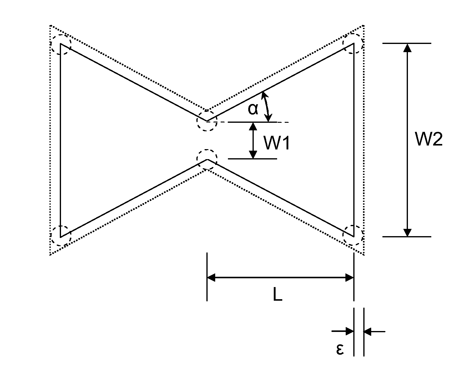
[0056]In the following, a geometry for a bulk-mode (BAW) MEMS resonator according to an embodiment of the invention is pre...


PUM


Abstract

A micro-electromechanical resonator suspended from an anchor. The resonator has: a length; a first width at a first distance from the anchor; and a second width at a second, greater distance from the anchor. The second width is greater than the first width, and the width of the resonator tapers gradually along at least part of its length from the second width to the first width.

Description

[0001]This application claims the priority under 35 U.S.C. §119 of European patent application no. 10166527.1, filed on Jun. 18, 2010, the contents of which are incorporated by reference herein.FIELD OF THE INVENTION[0002]This invention relates to optimisation of the geometry of Micro-Electromechanical Systems (MEMS) devices. In particular, it relates to the optimisation of the shape of a Bulk Acoustic Wave (BAW) resonator to provide a device with more stable characteristics, such as resonance frequency.BACKGROUND OF THE INVENTION[0003]MEMS resonator structures offer an attractive alternative to quartz resonators as frequency references for many applications because of their lower cost and reduced form factor.[0004]Temperature and process variations can impact the oscillation frequency of MEMS resonators beyond the tolerance limits of many applications. MEMS resonators are for example used in reference oscillators in RF receiver circuits. The resonance frequency of a MEMS resonator ...

Claims


Application Information

Patent Timeline
IPC IPC(8): H03B5/30
CPCH03H3/0076H03H2009/0233H03H2009/02251H03H9/2452
Inventor VAN DER AVOORT, CASPER
Owner NXP BV
Why Eureka
Try Eureka