Integrated Wireless Power Control Device

a wireless power control and wireless technology, applied in the direction of material dimension control, process and machine control, instruments, etc., can solve the problems of wasteful power consumption brought about by standby mode, environmental problems, and electrical power consumption. , to achieve the effect of less carbon, low cost and more economic us

Inactive Publication Date: 2011-12-22
UNIFIED PACKET SYST CORP
View PDF0 Cites 16 Cited by
  • Summary
  • Abstract
  • Description
  • Claims
  • Application Information

AI Technical Summary

Benefits of technology

[0010]One aim of this invention is to provide an integrated power control device and more specifically to simultaneously provide features such as zero-watt standby switching, overload protection, wireless remote control, power consumption acquisition and display, which allows electric appliances to be used more economically and to use less carbon, for example to provide a guaranteed level of safety and quality energy management support.
[0011]The present invention is characterized primarily by providing a system architecture having densely integrated features, and also equipping the applied electric appliances with features such as zero-watt standby switching, overload protection, wireless remote control, power consumption acquisition / display and wireless assistance to help an administrator in the energy management of the system through a computer. By means of the densely integrated software and hardware of the circuit control system, the coveted target of power system administrators, namely to provide low cost, plain equipment implementing minute energy management can be achieved.
[0012]The system comprises a microprocessor, responsible for the input, output, computation and storage of the information flow and a voltage-and-current detector, including a detecting circuit for the standby electrical signals and a detecting circuit for regular loads. The detection circuit is used to acquire the electrical signals for regular and standby loads, and to send the information back to the microprocessor and a data storage unit. The sampled data is used to calculate the frequency of the electrical signals, threshold value for the voltage-current alerting unit, the time to trip loads by means of computation of the microprocessor using a specific predetermined algorithm to activate the countdown by a counting unit in order to disconnect the power connection to the loads. The data storage unit stores the acquired electrical signals of the loads and supports the microprocessor by offering temporary or permanent digital data swapping and storage space. A display driver module receives and interprets control signals from the microprocessor, and is arranged to display the real-time electrical signals: voltage, current, energy consumed, over voltage and over current status information etc. An alarm output module is provided for driving an alarm circuit in response to receiving overloaded triggers from the microprocessor. A voltage-current alerting unit works in real-time to see whether the value of the total voltage or current of the loads exceeds its corresponding threshold value. The associated microprocessor may smooth the samples to avoid unnecessary false alarms. The microprocessor may issue a control signal to switch controls to execute an ON / OFF switching action on the sockets to assure the basic system safety requirement. A voltage / current / power computation unit is provided for computing the consumed energy of the associated voltage / current values which can be displayed under the control of the microprocessor and the display driver module.

Problems solved by technology

Taking one watt into account, a thousand electrical appliance loads operating for an hour will consume one degree of standby electrical power.
Given the present-day situation of serious electric power deficiencies, the power consumption brought about by standby modes is wasteful.
Moreover, electrical power consumption gives rise to environmental issues such as increased carbon usage.
Conventional wall switches and sockets, power extension cords and the majority of electrical appliances that serve direct circuit conduction have a limited capability for controlling the electric conduction of the load.
The amperage capacity of the circuit interrupter may be excessive and afford little protection for an individual electrical device.
For example, a load with a critical power rating below such a capacity may be damaged or may create damage if its rating is exceeded for an appreciable length of time.
The circuit interrupters fail to adequately protect appliances because a current overload which might be less than that required to open or burn out the interrupter, and still great enough to cause damage, can flow through the circuit interrupter unimpeded.

Method used


Image

  • Integrated Wireless Power Control Device
  • Integrated Wireless Power Control Device
  • Integrated Wireless Power Control Device

Examples


Embodiment Construction

[0024]The present invention includes a body and a plurality of sockets on the body. The appearance of the present invention is similar to a typical wall receptacle, wall switches or power extension cords.

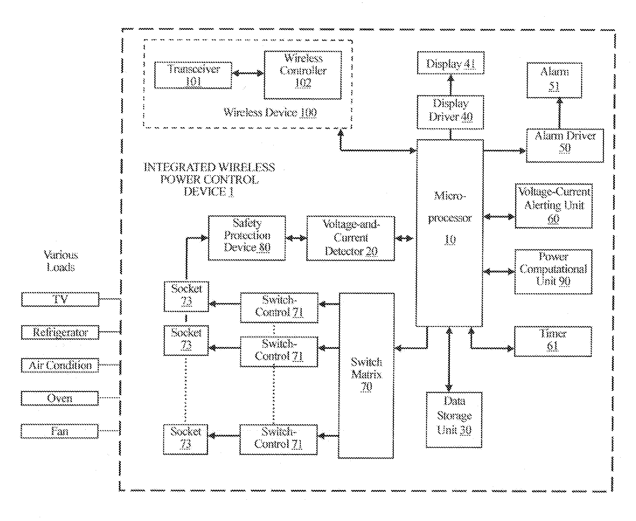
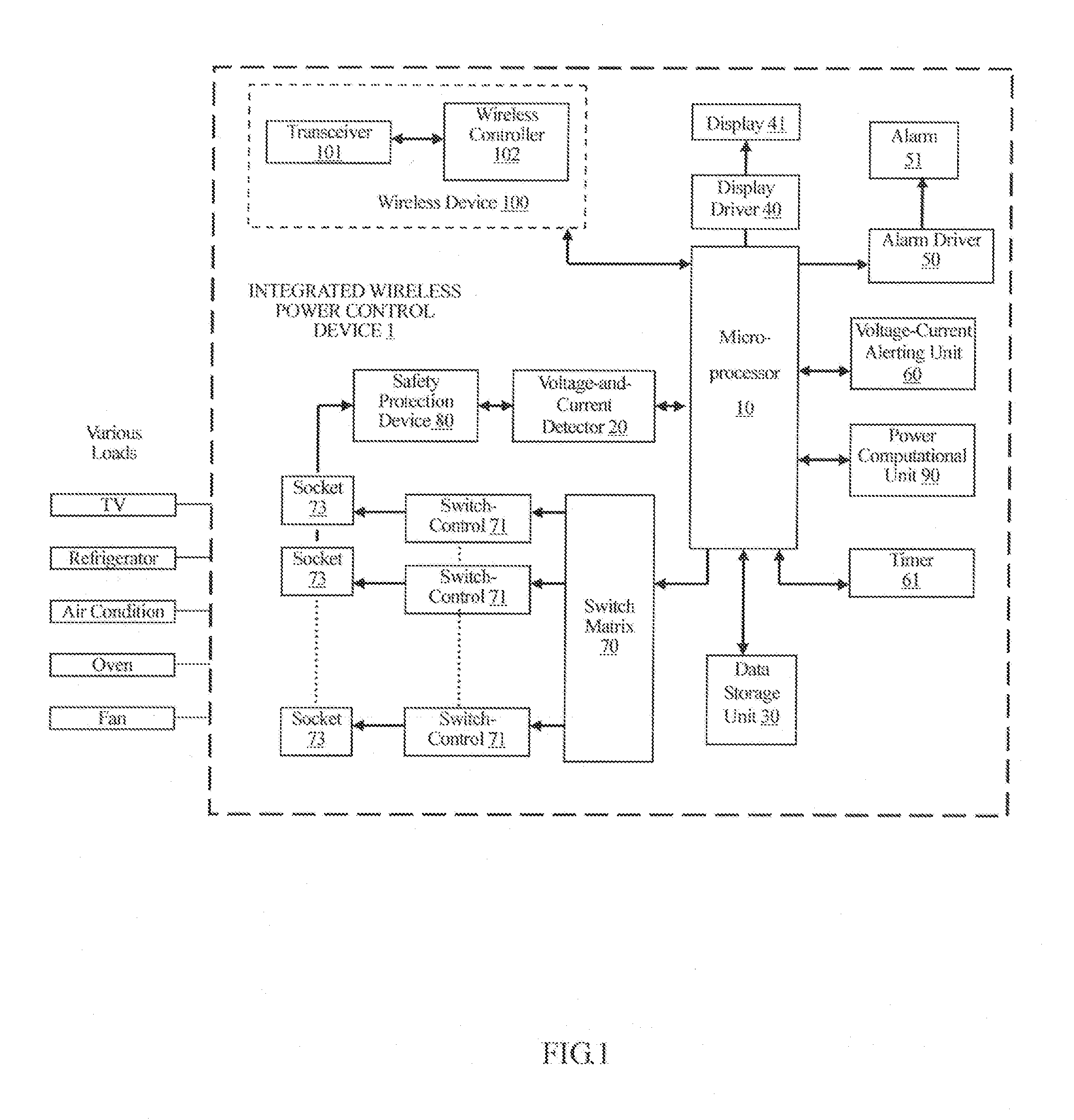
[0025]Please refer to FIG. 1, there is illustrated a functional block diagram of the present invention in accordance with a preferred embodiment of the integrated wireless power control device 1. A microprocessor (MCU) 10 is responsible for the input, output, computation and storage of associated data and information flow. The microprocessor 10 can be any digital data processing component, for instance an 8 / 16 / 32 / 64 bit processor, a field programmable gate array (FPGA) or a digital signal processor (DSP).

[0026]A voltage-and-current detector 20 is responsible for the acquisition of voltage and current signals of the total loads and for forwarding the signals to the microprocessor 10, a power computational unit 90 and a data storage memory unit 30 for temporary buffering or permanent ...


PUM


Abstract

An integrated power control device and method are provided. In one embodiment, a device includes a body, a plurality of sockets for connection with a load, and a plurality of switch-controls each connected with corresponding one of the sockets and controlling power connecting to the load. The device further includes a microprocessor for the input, output, calculation and control of data and information flow, wherein the microprocessor issues commands to the switch-controls to execute switch on or off on the sockets, a timer, and a data storage unit for data storage so as to provide the microprocessor to access the data. A voltage-and-current detector detects voltage and current values and stores them into the data storage through the microprocessor. A voltage-current alerting unit receives the voltage values and current values and informs the microprocessor when the values exceed predetermined thresholds. Finally, a power computational unit calculates power consumption of the load.

Description

CROSS REFERENCE TO RELATED APPLICATIONS[0001]This application is a divisional application of U.S. application Ser. No. 12 / 820,260, which was filed on Jun. 22, 2010, and is included herein by reference.FIELD OF THE INVENTION[0002]This invention relates generally to a integrated wireless power control device and, particularly, though not exclusively, to one that is provided with features such as zero-watt standby switching, overload protection, wireless remote control, power consumption acquisition and display, and which allows electrical appliances to be more economical and to use less carbon, preferably with a guaranteed level of safety and quality energy management support.BACKGROUND OF THE INVENTION[0003]In the daily life, an electric appliance load (for example, a TV set) has to keep its power ON during standby to enable the required remote control function. Under such circumstances, a typical electric appliance load will consume several tens of mA (milliampere) as per different ...

Claims


Application Information

Patent Timeline
Patent Type & Authority Applications(United States)
IPC IPC(8): G06F1/28
CPCH02H3/0935H02H3/247H02H3/207
Inventor LIN, WEI CHENG
Owner UNIFIED PACKET SYST CORP
Why Eureka
Try Eureka