System for producing and distributing compressed air

a technology of compressed air and system, applied in the direction of water mains, gas/liquid distribution and storage, pumping plants, etc., can solve the problem of not being able to remove it completely, achieve sufficient pressure dew point, improve internal oil separation of compressor packages, and save energy

Inactive Publication Date: 2007-07-10
OP SYST
View PDF12 Cites 12 Cited by
  • Summary
  • Abstract
  • Description
  • Claims
  • Application Information

AI Technical Summary

Benefits of technology

[0021]In conventional compressed air systems, the following compressed air treatment apparatuses are needed in the given order for instance when the pressurized dew point requirement is −40° C., as in pneumatic instrumentation systems, and an oil-sealed screw compressor is used: an actual compressor unit that contains, integrated into the same package, a suction air filter, an actual pressure-generating screw unit and a two-phase oil-separating cyclone and filter combination; a compressed air tank; an oil-separating filter; a fine oil-separating filter; an adsorption dryer; a dust filter; and sometimes also an active carbon filter and a bacterial filter. In addition, an oil trap is also needed. The compressed air system of the present invention does not require the suction air filter, compressed air tank or the other pressure-side filters, if used in the special case where the compressor is an oil-sealed screw compressor and the suction air is treated in such a manner that its pressurized dew point is sufficiently low and does not contain mechanical impurities. The adsorption dryer and the oil trap are then also unnecessary. Thus, all after-treatment devices are unnecessary. In addition, the compression process of the compressor can be made nearly isothermal by improving to a sufficient extent the oil cooling directed to the air being compressed between the screw elements. This is possible, because there is no moisture in the suction air. The internal oil separation of the compressor package is then improved so that practically all oil is separated, because no oil vapour is generated due to the low compression temperature. If for the purpose of saving energy, a higher than atmospheric pressure is to be used in the suction pipe, the pressure endurance of the suction side can easily be changed in a standard compressor and in a situation where the circulating compressor is a booster compressor, i.e. a pressure boost compressor.
[0022]If the system of the invention is leak-free, it is also possible to economically use other gases than air in it. One such gas is nitrogen. In a closed system like the one described herein, means for drying the gas are not needed. Only when the system is taken in to use, it is necessary to use either dried air or separate means for drying the air fed into the system.
[0023]In usage sites, from which the compressed air is led into return piping, the system of the invention also makes possible a procedure, in which after the usage site, the air pressure is not the normal atmospheric pressure, but even significantly higher than that. This type of compressed air drive connected to a return cycle can thus be arranged to first have a 10-bar pressure and afterwards a 3-bar pressure, in which case the pressure difference over the drive is 7 bars. Depending on the compressor properties, approximately 40% less energy is required to raise the air pressure from 3 bars to 10 bars than when raising the compressed air pressure from 0 bars to 7 bars. Thus, the use of a pressure level higher than the normal atmospheric pressure after the unit, and consequently in the suction pipe of the compressor, also reduces significantly the operating costs of the system. This is possible, because the force of a double-acting cylinder, for instance, is the same in both cases.

Problems solved by technology

In the present compressors, in which the compression is isentropic and, therefore, the compressed air is hot, oil enters as vapour into the piping and it is not possible to remove it completely and even reducing the amount requires specific filtering systems.

Method used


Image

  • System for producing and distributing compressed air
  • System for producing and distributing compressed air

Examples


first embodiment

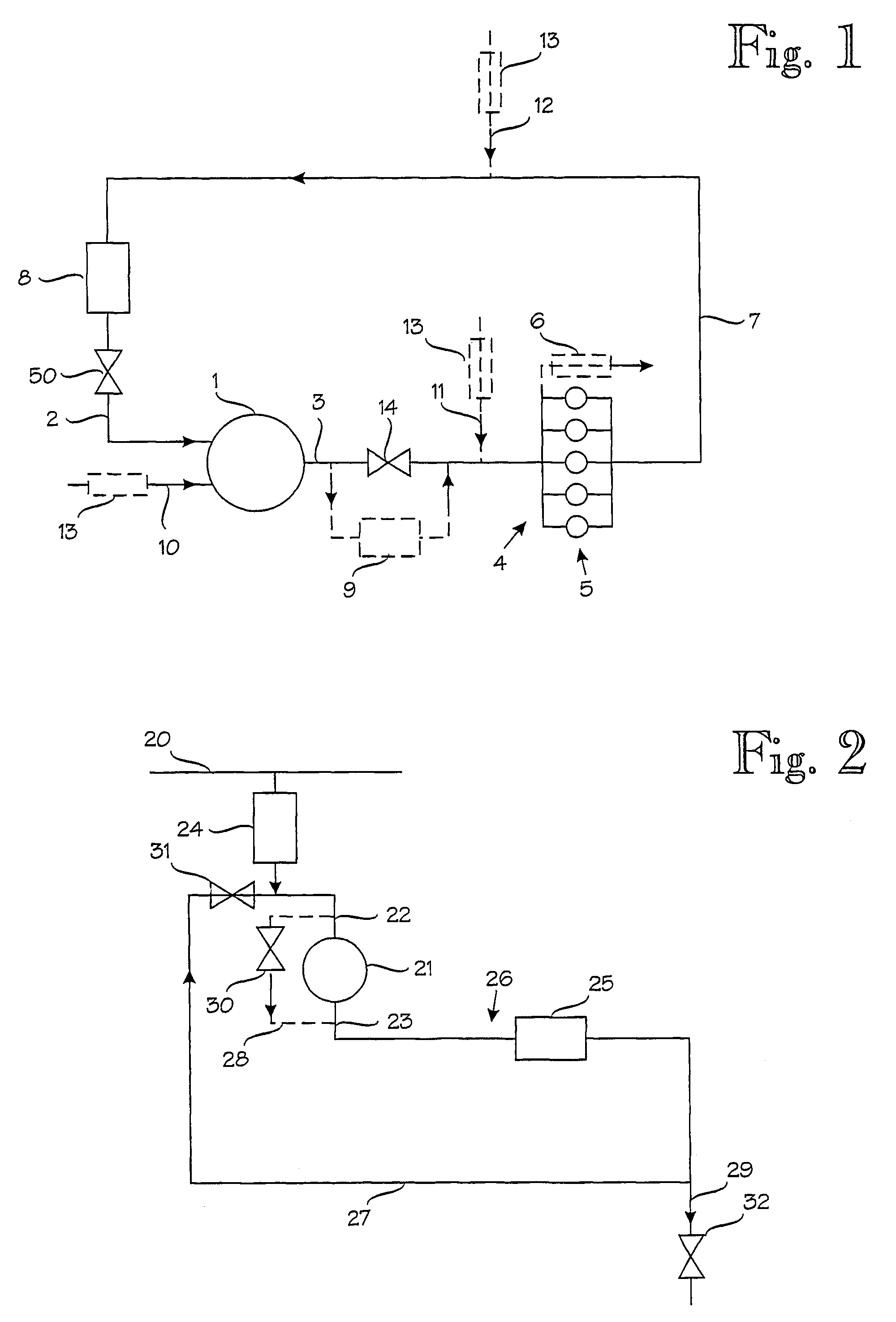
[0029]FIG. 1 shows by way of example a very simplified diagram of the system of the invention. This diagram includes only the components of a compressed air system that are essential for the invention. Thus for the sake of clarity, conventional and, in part, necessary devices of compressed air systems, such as after-treatment devices for the air produced in the compressor, for example an after-cooler, compressed air tank, dryer, oil separators or separating devices of other solid particles, are not shown.

[0030]The system shown in general in FIG. 1 comprises a compressor 1 with a suction pipe 2 and output pipe 3 connected to it. The output pipe 3 is connected to compressed air distribution piping 4 leading to devices 5, from which output air can be recovered. From the devices 5, a return pipe 7 leads to an air tank 8 that is, in turn, connected to the suction pipe 2 of the compressor 1. The tank 8 is, however, not necessarily needed in the system, especially if the volume of the retu...

second embodiment

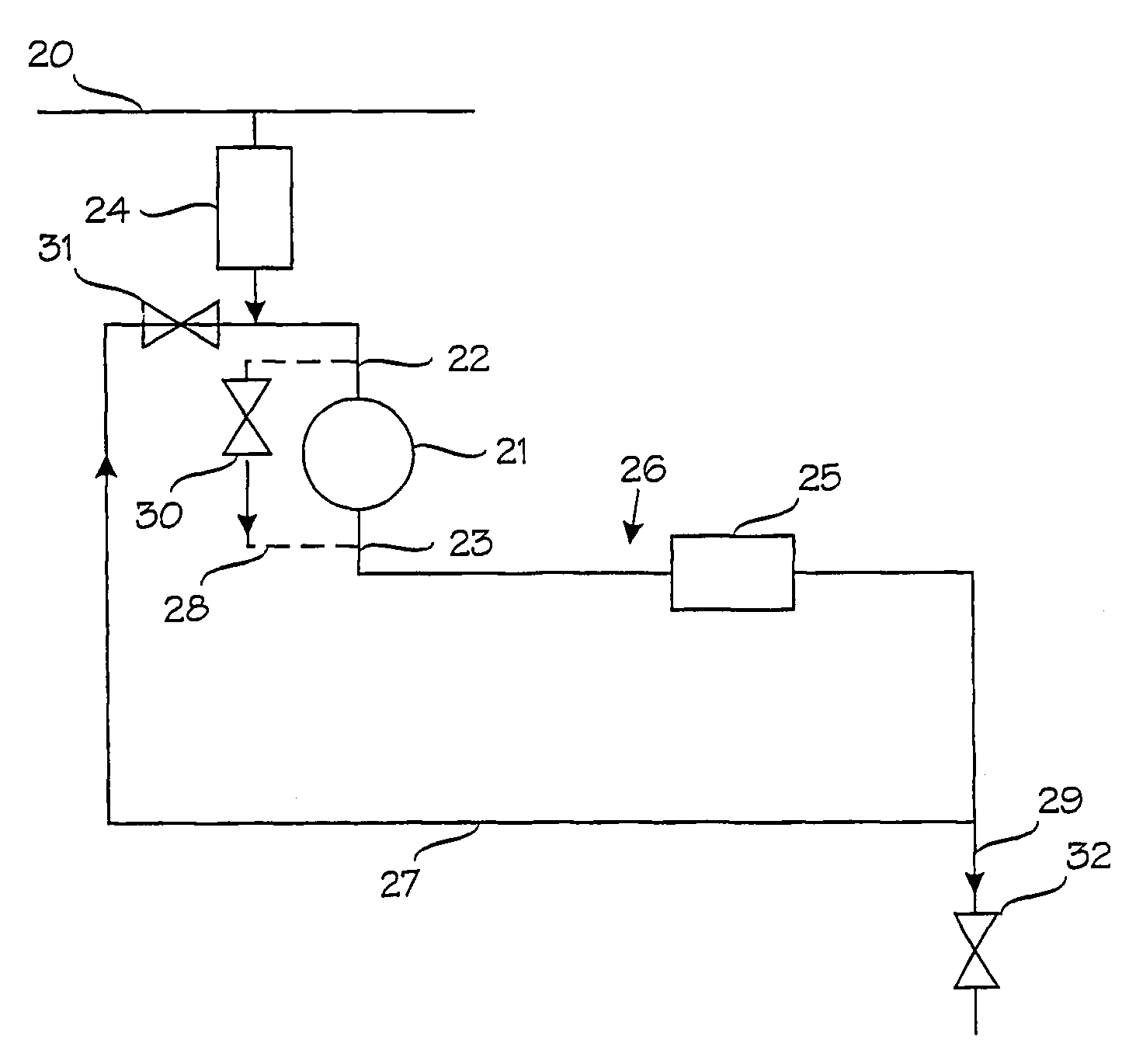
[0039]FIG. 2 shows by way of example a very general diagram of the system of the invention. In it, the sites of use of the system are marked with the reference numerals 25. In these sites, all air can be recovered. In this system of FIG. 2, a system that essentially corresponds to that of FIG. 1 is build around the drives 25 enabling air recovery. The system comprises at least one compressor 21 that has a suction pipe 22 and output pipe 23 feeding compressed air through distribution piping 26 to the drives 25, and a return pipe 27 that connects the drives to the suction pipe 22 of the compressor 21. The suction pipe 22 is connected to the compressed air distribution piping 20 of an industrial plant, for instance, by means of equipment 24 that contains at least a valve, which is possibly a pressure-reducing valve or pressure-regulating valve, through which additional air is released into the suction pipe 22 when necessary.

[0040]The compressed air distribution piping 20 belongs to a c...


PUM


Abstract

A system for producing and distributing compressed air that comprises at least one compressor (1) having connected thereto a suction pipe (2) for the intake of air and an output pipe (3) for air compressed by the at least one compressor, and distribution piping (4) connected to the output pipe (3) for distributing air to sites of use (5, 6). The system further comprises a return pipe (7) arranged between the suction pipe (2) and at least one site of use (5) for receiving air reduced in pressure in it and feeding it back to the at least one compressor (1).

Description

FIELD OF THE INVENTION[0001]The present invention relates to a system for producing and distributing compressed air that comprises at least one compressor having connected thereto a suction pipe for the intake of air and an output pipe for air compressed by said at least one compressor, and distribution piping connected to the output pipe for distributing air to sites of use.[0002]The invention also relates to a system for producing and distributing compressed air that comprises at least one compressor having connected thereto means for suction air intake and an output channel for air compressed by said at least one compressor, and distribution piping connected to the output channel for distributing air to sites of use.[0003]The invention thus concerns industrial and instrument air systems, in which the conventional pressure level is 10 to 15 bar or less, in which the pressurized dew point of the compressed air is generally appropriate for the intended purpose, i.e. even −40° C., an...

Claims


Application Information

Patent Timeline
Patent Type & Authority Patents(United States)
IPC IPC(8): F04B41/00F17D1/04F17D1/07
CPCF04B41/00F17D1/07Y10T137/85954Y10T137/86051
Inventor PARKKINEN, RAIMO
Owner OP SYST
Why Eureka
Try Eureka