Method and device for the preparation of foundry sand

a technology for foundry sand and mould sand, which is applied in the direction of cement mixing apparatus, mixing methods, mixing methods, etc., can solve the problems of inability to error-free and above all economically optimized operation, devices and/or peripheral equipment used and their method of operation, and inability to use error-free and above all economical optimization. , to achieve the effect of increasing the charging rate, saving resources and high quality

Inactive Publication Date: 2005-03-01
MASCHFAB GUSTAV EIRICH
View PDF6 Cites 14 Cited by
  • Summary
  • Abstract
  • Description
  • Claims
  • Application Information

AI Technical Summary

Benefits of technology

The object of the present invention is therefore to provide a method and a device for preparation of mould sand, which can be used economically without errors, and provides mould sands of uniform temperature and uniformly high quality in an economical manner and which, in comparison with the known mixers, has an increased charging rate.
A further particularly preferred version of the present invention provides that a feeder device for water is arranged in such a manner that the water is supplied through or along a preferably eccentrically arranged mixing tool with mixing paddles and fed into the mixture essentially in the region of the ends of the mixing paddles. Also in this case, according to the invention, the pressure difference between the mixing chamber and the outside environment is exploited. If water is to be fed into the mixture, a valve merely has to be opened. As a result of the vacuum pressure prevailing in the mixing chamber, the water is sucked through the feeder device directly into the mixture. The arrangement of the feeder device along a mixing tool has the advantage that the water can be fed directly into the mixture at different positions. In this context, the fluid outlet openings in the water feeder device are preferably arranged at different depths below the level of the mixture. Adequate mixing can therefore be achieved extremely quickly.

Problems solved by technology

Recycled sand generally has an increased temperature, for example, of between 100° C. and 140° C. Because sand temperatures above approximately 50° C. can present considerable problems to the moulding equipment, and at excessively high temperatures, uncontrollable evaporation losses over the distance between the mixer and the moulding equipment can lead to fluctuations in moisture in the ready sand, the sand must be cooled in this case.
However, the known stages of the method and the devices and / or peripheral equipment used and their method of operation are only suitable to a limited extent or not at all for use in a fully automated foundry moulding plant.
According to experience, error-free and above all economically optimized operation is not possible with the known method.
This is because, among other factors, the filling and emptying of the mixer is very time-consuming.
If it is rotated inwards, the closing mechanism must press the cover outwards against the sealing surface of the mixer with considerable force during vacuum operation.
However, the probability of contamination of the sealing surface increases considerably as the distance between the dosage funnel and filling opening and / or the dropping height of the substance to be charged increases.
For this reason, it is currently assumed, that a generic mixer cannot be manufactured economically with a large charging opening.
This results in a very long charging time and therefore also a very low plant performance.
If the mixer is loaded too quickly, an excess air pressure rapidly builds up as a result of compression of the air in the mixer.
This means that the plant must be cleaned more frequently which, once again, is associated with higher costs and undesired interruptions of operation.
For this reason, it has generally been considered that, on the one hand, the charging rate cannot be further increased, because larger input openings cannot be realized in an economical manner.

Method used


Image

  • Method and device for the preparation of foundry sand
  • Method and device for the preparation of foundry sand
  • Method and device for the preparation of foundry sand

Examples


Embodiment Construction

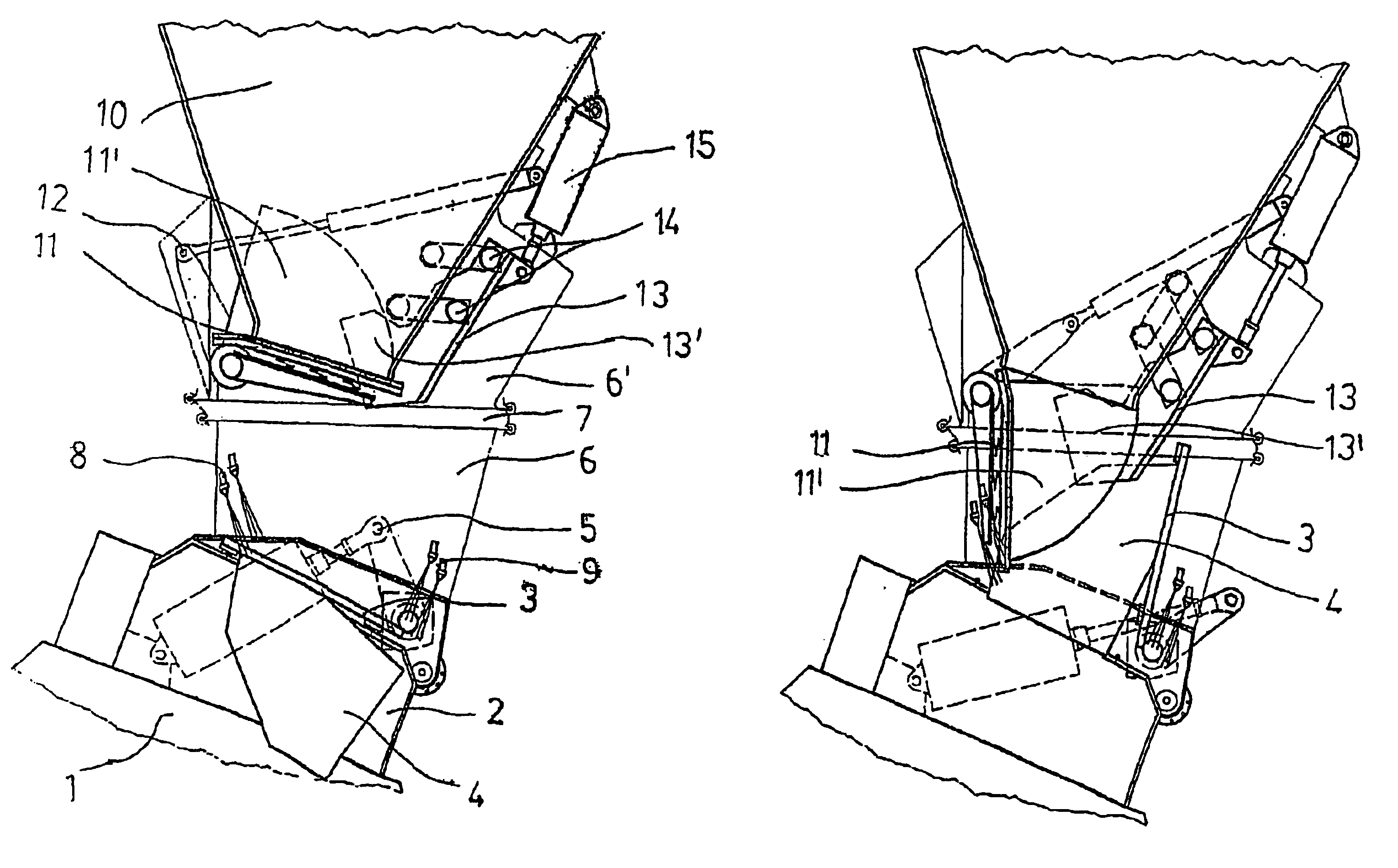
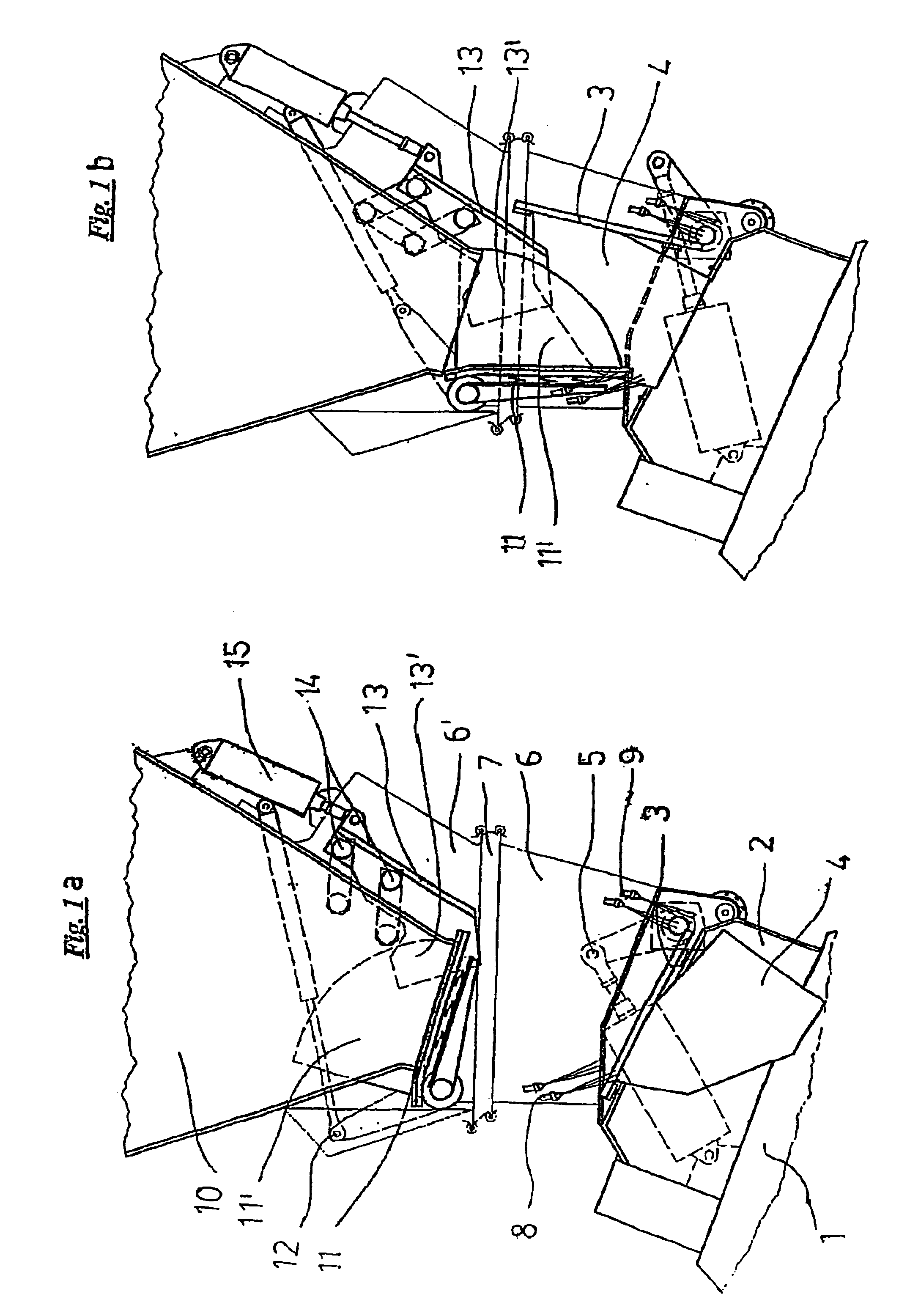
FIGS. 1a) and 1b) show the outlet region of a solids weighing device 10 and the inlet region of the mixer 1. The solids weighing device 10 is used for determining the quantity of recycled sand to be supplied or optionally also of other mixture components. In FIG. 1a), both the mixer 1 and the solids weighing device 10 are closed, while FIG. 1b) shows the conveyance position between the mixer 1 and the solids weighing device 10.

An inlet connecting piece 2 is arranged at the upper side of the mixer 1. This inlet connecting piece 2 is sealed in a vacuum-tight manner through the container cover 3 with the assistance of the lever arm 5, which is driven, for example, by a hydraulic cylinder. It can be seen that the container cover 3 provides one lateral cheek 4 at both of its lateral outer edges.

The solids weighing device 10 also has an outlet flap 11, which provides lateral cheeks 11′ at both of its lateral outer edges. This flap can be opened or closed via the lever 12.

Moreover, this ve...


PUM

PropertyMeasurementUnit
areaaaaaaaaaaa
volume flow rateaaaaaaaaaa
areaaaaaaaaaaa

Abstract

A device for preparing moulding sand. The device includes a mixer configured to operate under at least a partial vacuum and at least one feeder to introduce components to be mixed. An inlet in the mixer is of sufficient size to allow rapid introduction of the components into the mixer from the feeder. The combination of large inlet opening and a pressure differential between the mixer and the feeder significantly reduces the time required to fill the mixer. In addition, the presence of the pressure differential made possible by the vacuum in the mixer reduces the likelihood that airborne contaminants resident in the mixer will migrate outside the mixer. Optional moveable conveyor chutes minimize contact of airborne contaminants with adjacent equipment, while optional mixing tools facilitate the introduction of powdered additives into the mixer.

Description

BACKGROUND OF THE INVENTIONThe present invention relates to a method and a device for the preparation of mould sand using a mixing process in a mixer, wherein the preparation takes place at least partially under vacuum.The preparation of sand for the manufacture of moulds is intended to produce the correct mixing ratio of grain sizes and of proportions of quartz sand, binding agent, coal dust, optionally other additives as well as recycled and new sand, to homogenise the mixture and, in this context, to coat the grains with the binding agent to a large extent, to adjust the correct moisture content, to adjust the correct temperature of the mould sand and finally to convey the ready-prepared sand to the places of use.Recycled sand generally has an increased temperature, for example, of between 100° C. and 140° C. Because sand temperatures above approximately 50° C. can present considerable problems to the moulding equipment, and at excessively high temperatures, uncontrollable evapor...

Claims


Application Information

Patent Timeline
Patent Type & Authority Patents(United States)
IPC IPC(8): B01F3/12B01F15/02B22C5/08B22C5/04B22C5/00B22C5/18B01F13/00B01F13/06B01F7/00
CPCB01F3/1228B22C5/185B22C5/044B22C5/08B01F15/0201B01F7/00258B01F13/06B01F2015/0221B01F23/54B01F27/1121B01F27/2122B01F33/70B01F35/715B01F35/71
Inventor GREISSING, UWEADELMANN, DIETEREIRICH, PAULDURR, HERBERTDIEM, WINFRIED
Owner MASCHFAB GUSTAV EIRICH
Why Eureka
Try Eureka