
Control device for an automated geared transmission

a control device and gear shift technology, applied in mechanical equipment, propulsion parts, transportation and packaging, etc., can solve the problem of not being able to simultaneously supply the supply output, and achieve the effect of reducing the supply output and preventing the supply pressure from increasing

Inactive Publication Date: 2011-12-29
DAIMLER AG
View PDF4 Cites 51 Cited by
  • Summary
  • Abstract
  • Description
  • Claims
  • Application Information

AI Technical Summary

Benefits of technology

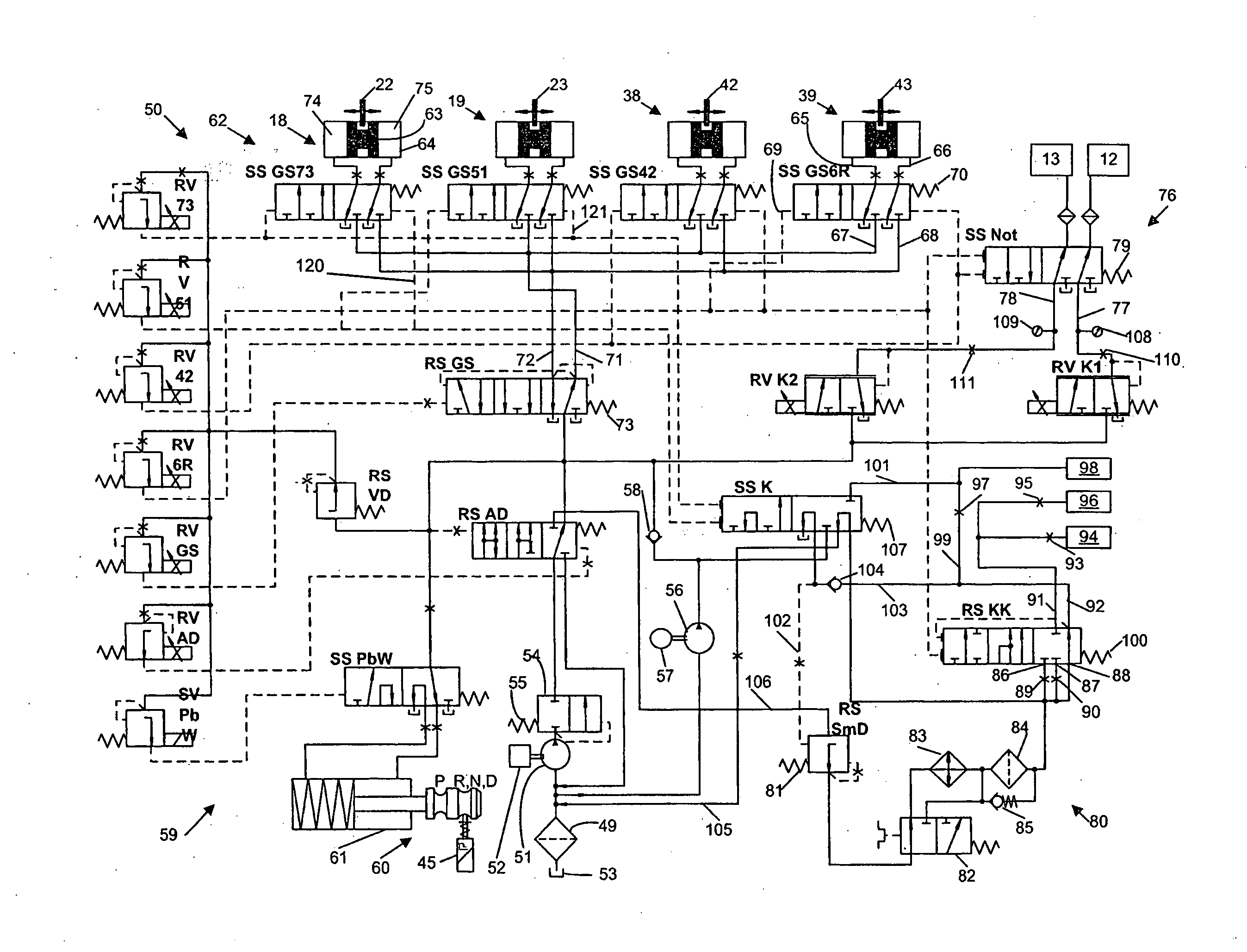
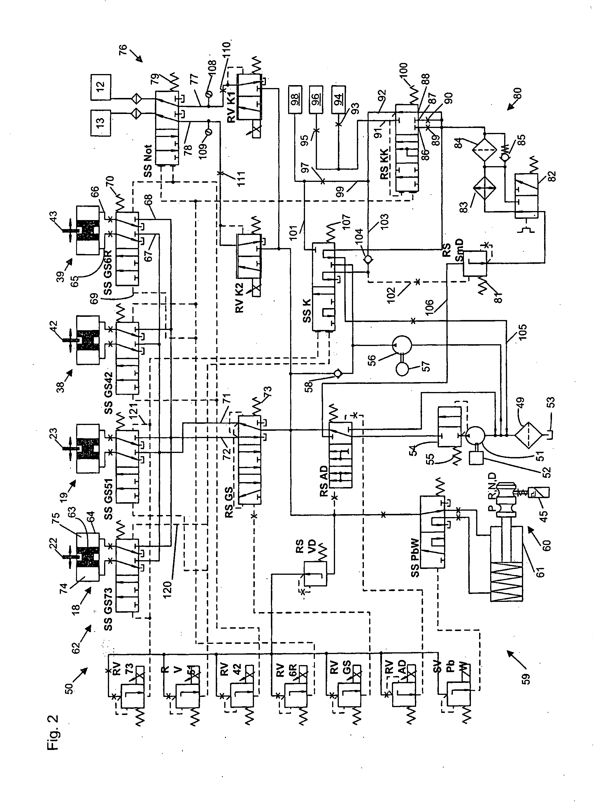
[0017]The second gear shift control pressure of the second gear shift slide thereby counteracts the first gear shift control pressure of the first gear shift slide, whereby the first gear shift slide can be blocked by the second gear shift control pressure.
[0019]A safe blocking of the gears of a partial transmission is thereby achieved in a simple manner. Additionally, further functions within the control device can also be realized by means of the gear shift control pressures. For example, the first gear shift control pressure can be increased after the second gear shift device was selected by means of the second gear shift control pressure, without the first gear shift device having to be selected additionally to the second shift device. In this state, the behavior of a lubricating cooling system can for example be influenced by means of the first gear control pressure.
[0020]The gear shift actuation system is designed according to the invention in such a manner that the second shift device is selected when the second gear shift control pressure exceeds a first pressure threshold. The second gear shift control pressure acts against a spring, so that the respective pressure limit is determined by the properties of the spring. When the second gear shift control pressure exceeds a second pressure threshold, an adjustment of an actuation pressure at the first shift device by means of the first gear shift control pressure is no longer possible. The second pressure threshold can be the same or smaller than the first pressure threshold. A safe blocking of the first shift device is made possible thereby.

Problems solved by technology

It is therefore not possible that a supply pressure is present simultaneously at both supply outputs.

Method used


Image

  • Control device for an automated geared transmission
  • Control device for an automated geared transmission
  • Control device for an automated geared transmission

Examples


Embodiment Construction

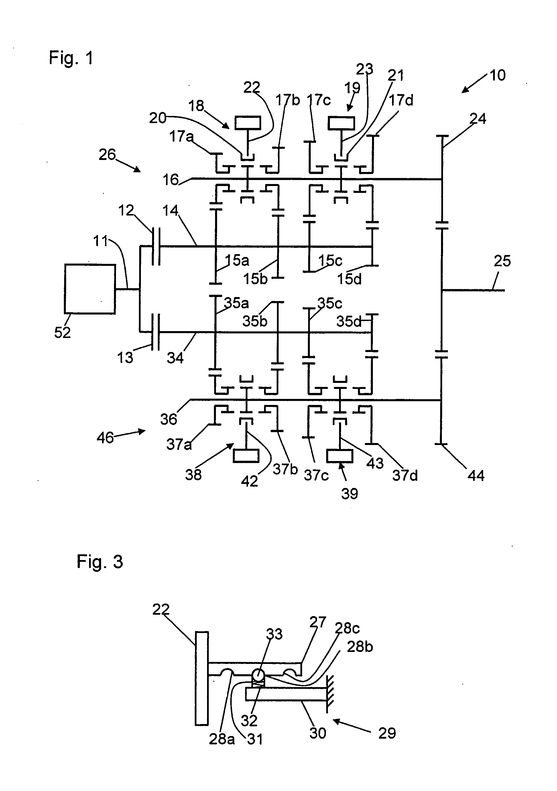
[0031]FIG. 1 shows an automated transmission in the form of a dual clutch transmission 10 for a motor vehicle with seven forward and one reverse gear which is connected via a drive shaft 11 to a drive machine 52, for example an internal combustion engine. The drive shaft 11 is in operative connection with a first and a second clutch 12, 13. The clutches 12, 13 serve as start-up clutches and are particularly designed as wet friction clutches, which can be actuated hydraulically. The first clutch 12 is additionally in operative connection with a first transmission input shaft 14, on which are arranged four fixed wheels 15a to 15d. A first countershaft 16 is arranged parallel to the first transmission input shaft 14, on which countershaft are mounted four idler wheels 17a to 17d in a rotatable manner, which, respectively, cog with the fixed wheels 15a to 15d of the first transmission input shaft 14. The idler wheels 17a, 17b can be coupled to the countershaft 16 in a rotationally fixed...


PUM


Abstract

In a control arrangement for an automated gear shift transmission, particularly a dual clutch transmission, which provides for a plurality of functionalities with a relatively small number of slides and control valves, a first gear slide, which is assigned to a first shift device and by means of which an actuation pressure can be applied to the first shift device, has a first and a second supply input for the first and second movement direction of the piston. A supply pressure slide, by means of which a supply pressure can be directed to the gear slide, has first and second supply outputs, which are respectively connected to the first and second supply inputs of the gear slide. The supply pressure slide is designed in such a manner that it can direct a supply pressure optionally to one of the two supply outputs.

Description

[0001]This is a Continuation-In-Part application of pending international application PCT / EP2009 / 009043 filed Dec. 16, 2009 and claiming the priority of German application 10 2009 005 755.2 filed Jan. 23, 2009.BACKGROUND OF THE-INVENTION[0002]The invention relates to a control arrangement for an automated gear shift transmission, particularly a dual clutch transmission with first and second partial transmissions in which different gears can be engaged by coupling idler wheels to a shaft.[0003]EP 1 635 091 A1 discloses a hydraulic control device for an automated geared transmission in the form of a dual clutch transmission with two partial transmissions for a motor vehicle. The different gears of the dual clutch transmission can be engaged and disengaged by means of shift devices in the form of shift cylinders acting in a dual manner. For engaging and disengaging a gear, a cylinder of the shift cylinder acting on both sides can be moved into a first and a second direction. The gear t...

Claims


Application Information

Patent Timeline
IPC IPC(8): F16H63/34
CPCF16H61/16Y10T74/20024F16H2061/1204Y10T74/19228F16H61/688F16H61/2807Y10T74/19251
Inventor BRANDENBURG, MARKUS
Owner DAIMLER AG
Learn More