Overhead sanitization system

Inactive Publication Date: 2011-12-29
LELLA CHRISTOPHER +1
View PDF3 Cites 7 Cited by
  • Summary
  • Abstract
  • Description
  • Claims
  • Application Information

AI Technical Summary

Benefits of technology

[0011]It is an object of the present invention, therefore, to provide an arrangement which allows for a simple and effective sanitization of all those areas where people tend to congregate, and where they are at the greatest risk of becoming sick or otherwise infected.

Problems solved by technology

But those methods leave much to be desired, especially in an age where the proprietors are in an economic fix, unable to disburse for these services funds which may not be available, or which are tight in their distribution.
Purchases of cleaning machines and equipments have been curtailed for similar economic reasons, with the overall result being an increase in the amount of complaints being made of bacterial and other germ infections.

Method used


Image

  • Overhead sanitization system
  • Overhead sanitization system

Examples


Embodiment Construction

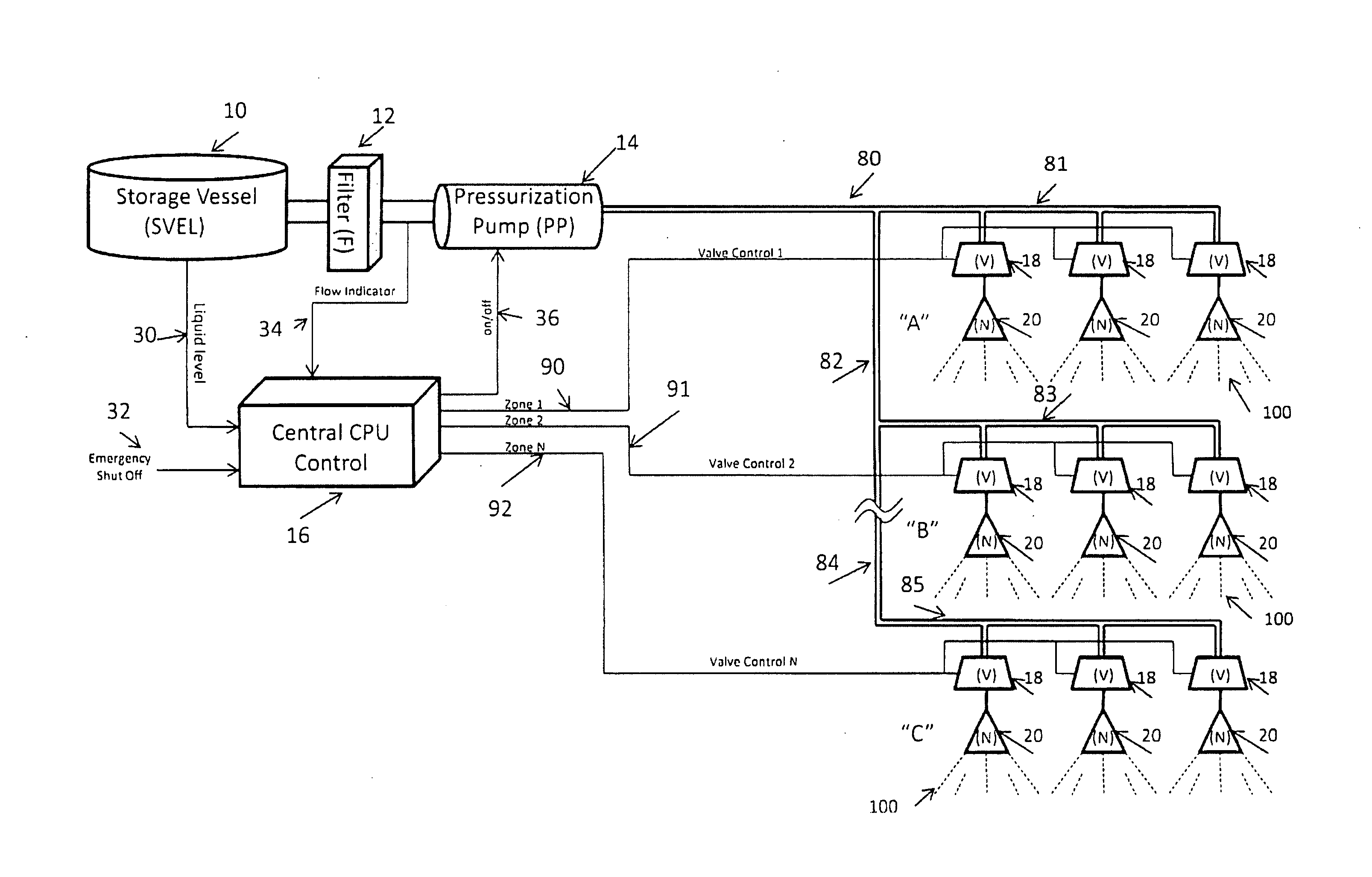
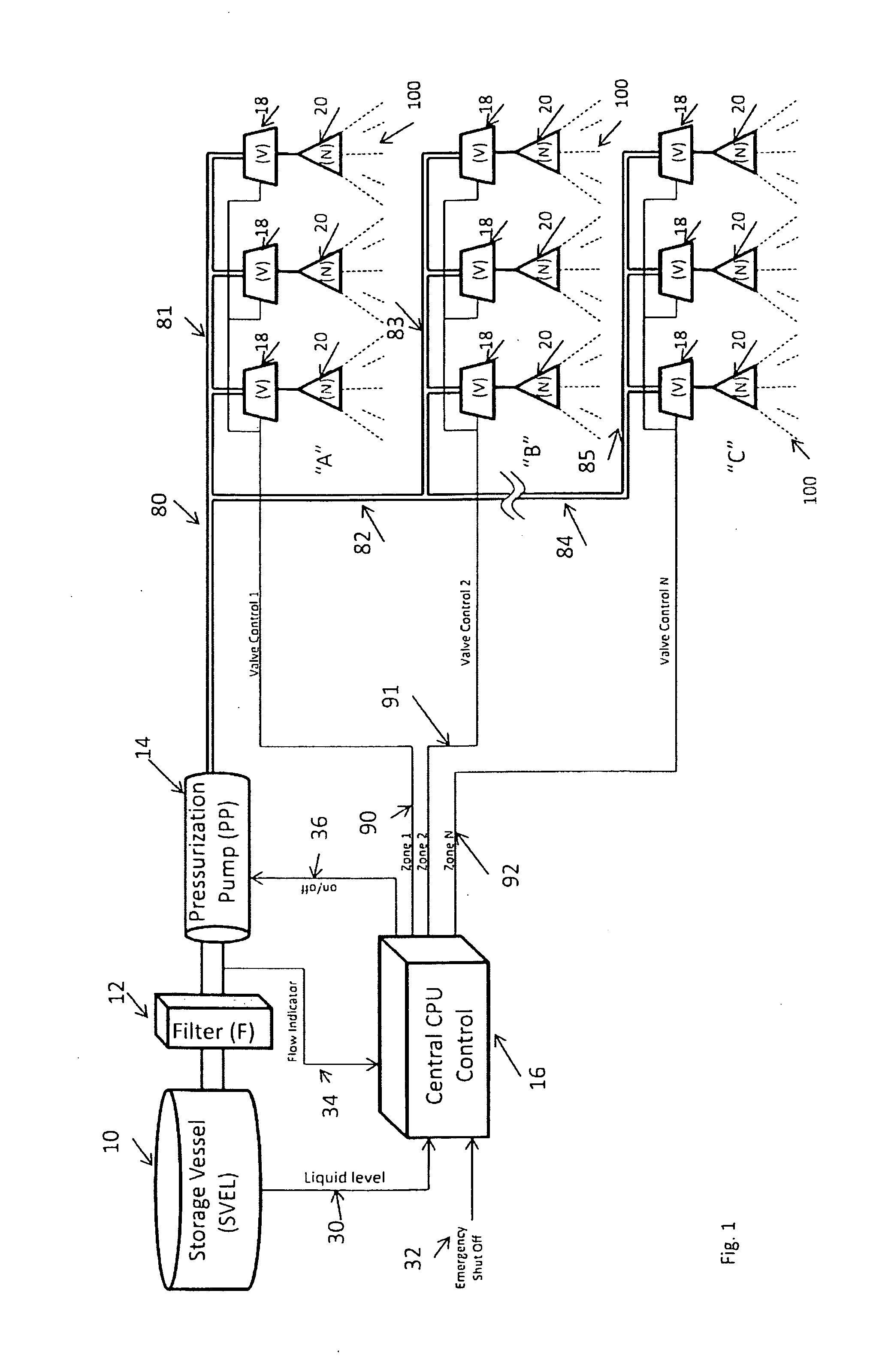
[0016]The overhead sanitization system—whether permanently installed in the ceilings of hospitals, hospital rooms, nursing homes, schools, medical offices, stadiums, or in such movable systems as buses, trains, and airplanes, for example—includes a storage vessel 10, a filter 12, a pressurization pump 14, a central computer processing CPU control 16, and one or more control valves 18 and nozzle heads 20. Three sets of control valves and nozzle heads are shown at “A”, as in various locations on the first floor of a school facility, three sets of control valves and nozzle heads are shown at “B” for various locations on the second floor of the school, and three sets of control valves and nozzle head are illustrated at “C” for locations at upper floors, serially, at the school, location.

[0017]In a preferred embodiment of the invention, the storage vessel 10 may be constructed of a plastic material selected to be resistant to the antibacterial spray; but where increased durability is des...


PUM


Abstract

An overhead sanitization system utilizing ceiling embedded control valves and nozzle heads operative to provide an antibacterial spray under the control of a central computer processing unit monitoring the fluid level within an antibacterial solution storage vessel, and with the control valves and heads being supplied with the antibacterial solution from the storage vessel under the computer unit's control of a pressurization pump coupled to the storage vessel by an included impurity eliminating filter.

Description

CROSS-REFERENCE TO RELATED APPLICATIONS[0001]A Provisional Patent Application covering the invention described herein was filed on May 21, 2010, and assigned Serial No. 61 / 396,002.STATEMENT REGARDING FEDERALLY SPONSORED RESEARCH OR DEVELOPMENT[0002]Research and development of this invention and Application have not been federally sponsored, and no rights are given under any Federal program.REFERENCE TO A MICROFICHE APPENDIX[0003]Not ApplicableBACKGROUND OF THE INVENTION[0004]1. Field of the Invention[0005]This invention relates to a non-sticky, non-staining, eco-friendly sanitization system, in general, and to such a system for use at a fixed or movable structural installation, in particular.[0006]2. Description of the Related Art[0007]As will be appreciated, more and more people every day are becoming more and more germophobic.[0008]It is not unusual, for example, for a situation to develop where one sick child in a classroom infects the rest of the class to the extent that many ot...

Claims


Application Information

Patent Timeline
IPC IPC(8): B08B3/02
CPCA61L2/22A61L2202/14A61L2202/15A61L2202/25
Inventor LELLA, CHRISTOPHERLELLA, SHARI
Owner LELLA CHRISTOPHER
Why Eureka
Try Eureka