Wicker-Type Face Seal and Wellhead System Incorporating Same

a wellhead and face seal technology, applied in the direction of engine seals, sealing/packing, borehole/well accessories, etc., can solve the problems of compromising the seal and all the seals fail to maintain pressure integrity, and achieve enhanced pressure, seal pressure, and pressure enhanced

Inactive Publication Date: 2011-12-29
VETCO GRAY
View PDF16 Cites 15 Cited by
  • Summary
  • Abstract
  • Description
  • Claims
  • Application Information

AI Technical Summary

Benefits of technology

[0005]In an embodiment of the present technique, a seal assembly is provided that comprises: an annular seal located in a pocket defined by a wellhead bore and the exterior portion of an inner wellhead member such as a bridging hanger, and a face seal formed by opposing sealing surfaces on a bridging hanger and casing hanger. In this embodiment, a wicker profile is preferably formed onto the downward facing sealing surface that bites into the opposing seal surface. The wicker profile may be hardened. These features provide robustness in maintaining the integrity of the face seal. Backup seals may also be located within recesses formed on the downward facing sealing surface.
[0007]When used on a bridging hanger, the face seal is pressured enhanced due to the net downward load on the bridging hanger. With pressure from below, the angled surface of the top of the hanger could act to increase contact forces as well, making the seal pressure enhanced from both directions.
[0008]This face seal design may also be used for a sealing lockdown hanger, in which case a lock ring on the lockdown hanger creates a sufficient load to force the wicker profile to bite into the opposing sealing surface to form a face seal. Further, the hanger can be sized so that the isolation sleeve seals into a bore larger than the inner diameter face wicker, allowing the face seal to be pressure enhanced in the primary direction as well. A wicker-type face seal on a sealing lockdown hanger will allow the isolation sleeve to tie directly into the lockdown hanger, significantly shortening the isolation sleeve and in turn the guide funnel and tree height. Tying into the lockdown hanger also allows for standardization on the short isolation sleeve instead of having to create custom solutions specific for each project.
[0009]This use of field proven wicker technology to form improved face seals between wellhead members maintains production integrity and provides a robust metal-to-metal seal for contingency and production use. In addition, the use of the improved face seal on lockdown hangers will lower the time and cost involved in isolation sleeve installations due to the shorter length and standardization of the isolation sleeve.

Problems solved by technology

However, sometimes all of these seals fail to maintain pressure integrity and contingency sealing measures must be taken.
The elastomeric seal may degrade, or become damaged, thus compromising the seal that the contingency option needed to provide.
This same problem may occur between lockdown hangers sealing to a hanger below and in addition may require the use of a long isolation sleeve extending to the hanger below when such is required.

Method used


Image

  • Wicker-Type Face Seal and Wellhead System Incorporating Same
  • Wicker-Type Face Seal and Wellhead System Incorporating Same
  • Wicker-Type Face Seal and Wellhead System Incorporating Same

Examples


Embodiment Construction

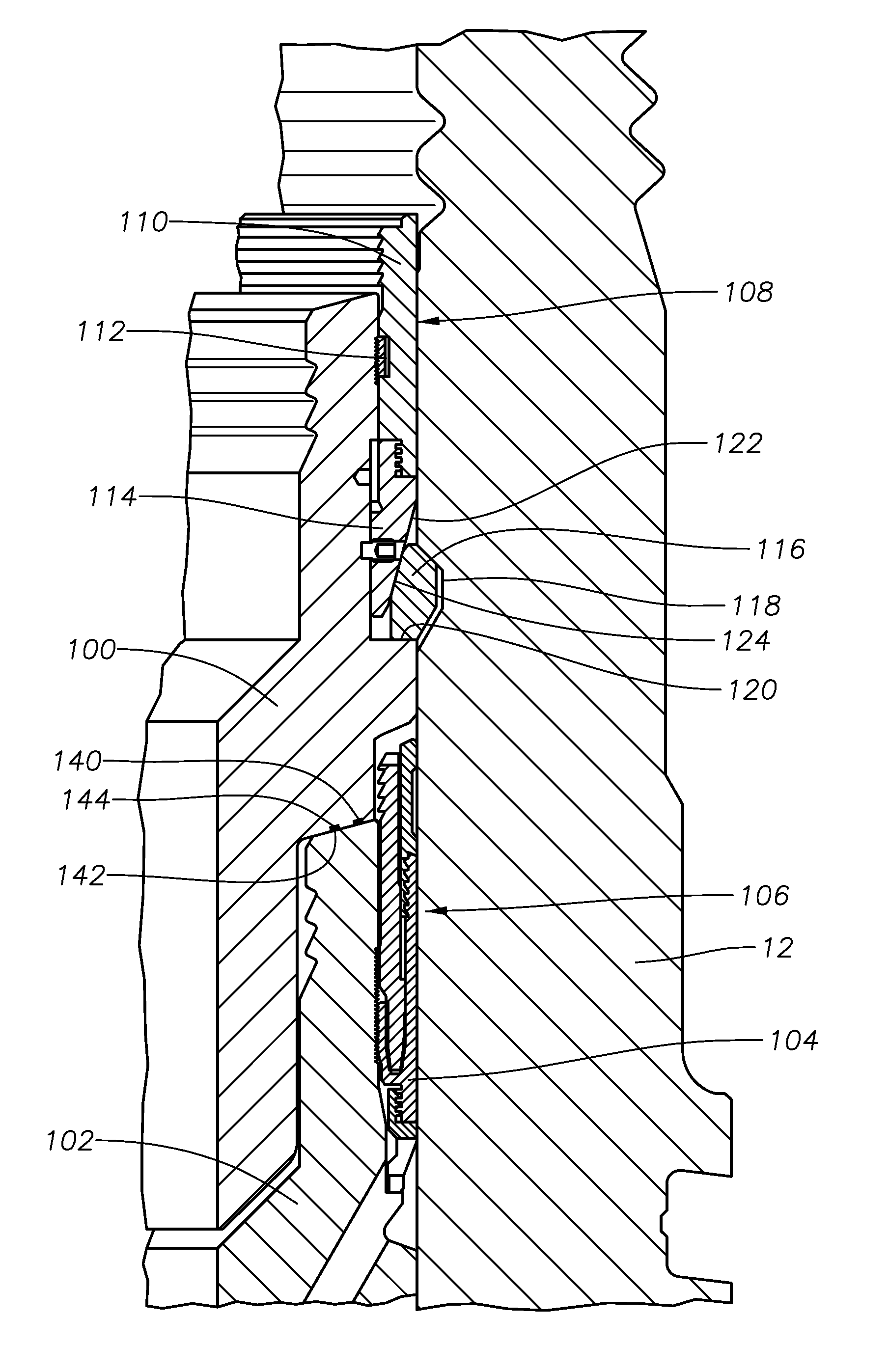
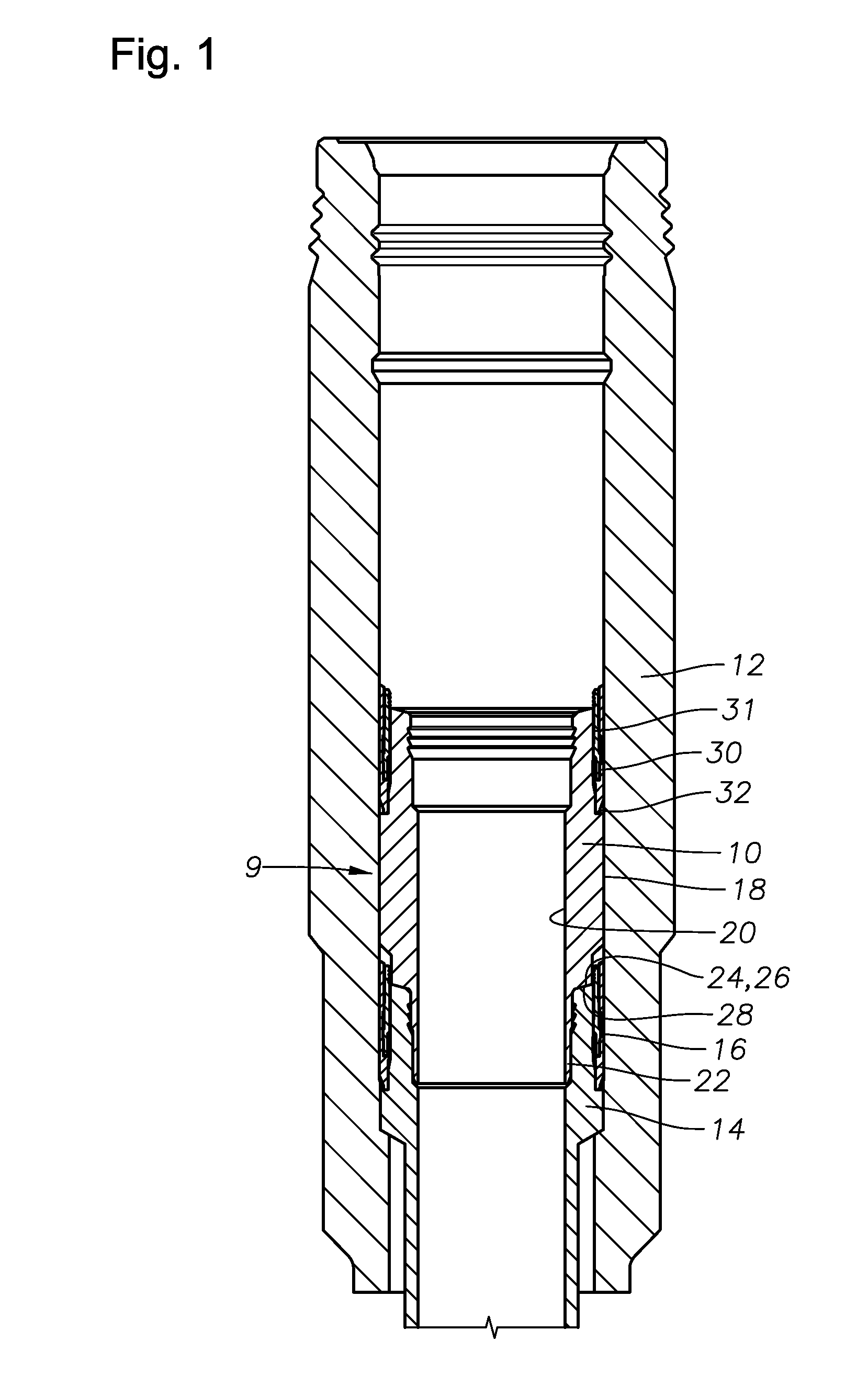
[0021]Referring to FIG. 1, an embodiment of the invention shows a portion of a seal assembly 9 located between an outer wellhead 12 and an inner wellhead member 10. In the illustrated embodiment, the outer wellhead 12 is a high pressure housing. The inner wellhead member 10 may be a bridging hanger that is landed on an existing casing hanger 14. However, it may be a second casing hanger landed on an existing casing hanger in a stacked arrangement. Typically, the bridging hanger 10 is landed on the casing hanger 14 when an annular seal 16, located between the wellhead 12 and the casing hanger 14, has failed. The bridging hanger 10 has an exterior cylindrical surface 18 and an interior profile 20. When landed, a lower portion 22 of the bridging hanger 14 internally extends into a corresponding profile formed in the casing hanger 14 interior.

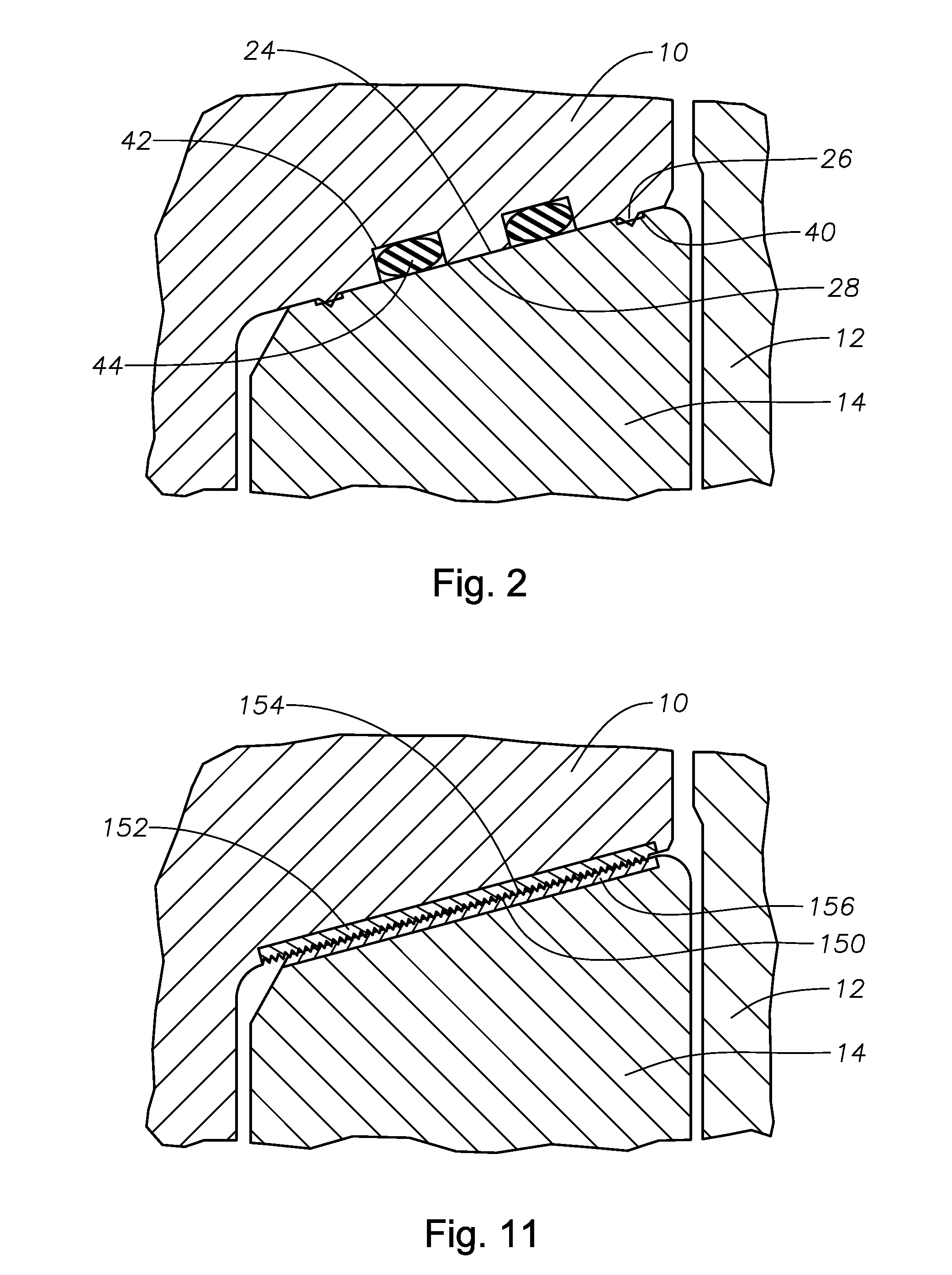
[0022]Continuing to refer to FIG. 1, face sealing surfaces 24, 28, form a face seal as they sealingly engage each other when axially energized. As...


PUM


Abstract

A wellhead seal assembly that forms a metal-to-metal seal between inner and outer wellhead members and a face seal between inner wellhead members. The face seal is created by two opposing sealing surfaces on inner wellhead members that sealingly engage each other. The inner wellhead members that interact to form a face seal may be a casing hanger, bridging hanger, or lockdown hanger. A wicker profile formed on one of the opposing seal surfaces bites into the opposing seal surface in response to a load. The face seal is designed such that well pressure enhances the face seal.

Description

FIELD OF THE INVENTION[0001]This invention relates in general to wellhead assemblies and in particular to a seal for sealing between wellhead members.BACKGROUND OF THE INVENTION[0002]Seals are used between inner and outer wellhead members to contain internal well pressure. The inner wellhead member may be a casing hanger located in a wellhead housing that supports a string of casing extending into the well. Alternatively, the inner wellhead member could be a tubing hanger that supports a string of tubing extending into the well for the flow of production fluid. The tubing hanger lands in an outer wellhead member, which may be a wellhead housing, a Christmas tree, or a tubing head. A packoff or seal, seals between the inner wellhead member and the outer wellhead member. In addition, emergency annulus seals can be used in case the packoff seal fails.[0003]However, sometimes all of these seals fail to maintain pressure integrity and contingency sealing measures must be taken. Bridging ...

Claims


Application Information

Patent Timeline
Patent Type & Authority Applications(United States)
IPC IPC(8): E21B33/03
CPCE21B33/0422E21B33/03E21B33/04
Inventor GETTE, NICHOLAS PETERFAZ, ARMANDOELLIS, STEPHEN
Owner VETCO GRAY
Why Eureka
Try Eureka