Intensity and color display for a three-dimensional metrology system

a three-dimensional metrology and intensity display technology, applied in the field of noncontact three-dimensional metrology, can solve the problems of difficult interpretation of 3d point clouds displayed on a monitor, image typically appears significantly different from a direct observation of the object surface,

Inactive Publication Date: 2011-12-29
DENTAL IMAGING TECH
View PDF27 Cites 63 Cited by
  • Summary
  • Abstract
  • Description
  • Claims
  • Application Information

AI Technical Summary

Problems solved by technology

3D point clouds displayed on a monitor are typically difficult for a user to interpret, especially if at least one portion of the displayed surface is behind another portion of the displayed surface.
Although these techniques can improve the ability to properly interpret the displayed 3D data, the resulting images typically appear significantly different from a direct observation of the object surface.

Method used


Image

  • Intensity and color display for a three-dimensional metrology system
  • Intensity and color display for a three-dimensional metrology system
  • Intensity and color display for a three-dimensional metrology system

Examples


Embodiment Construction

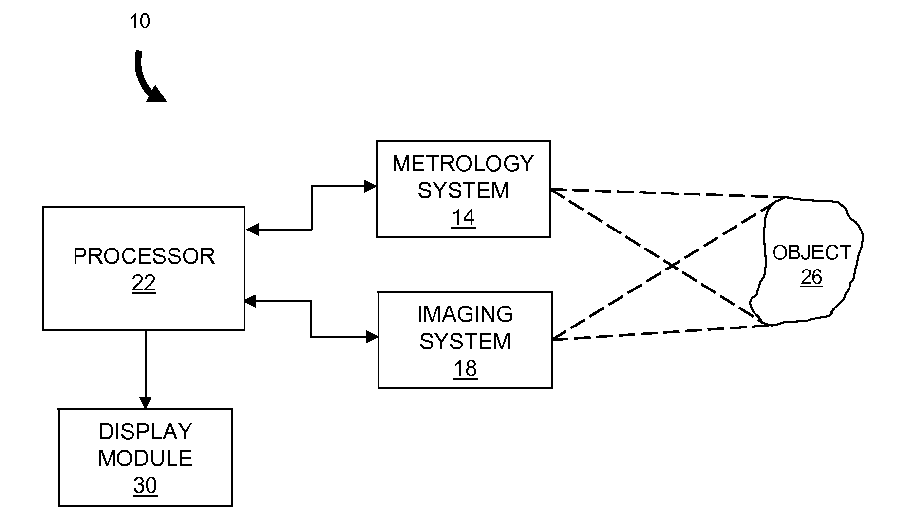
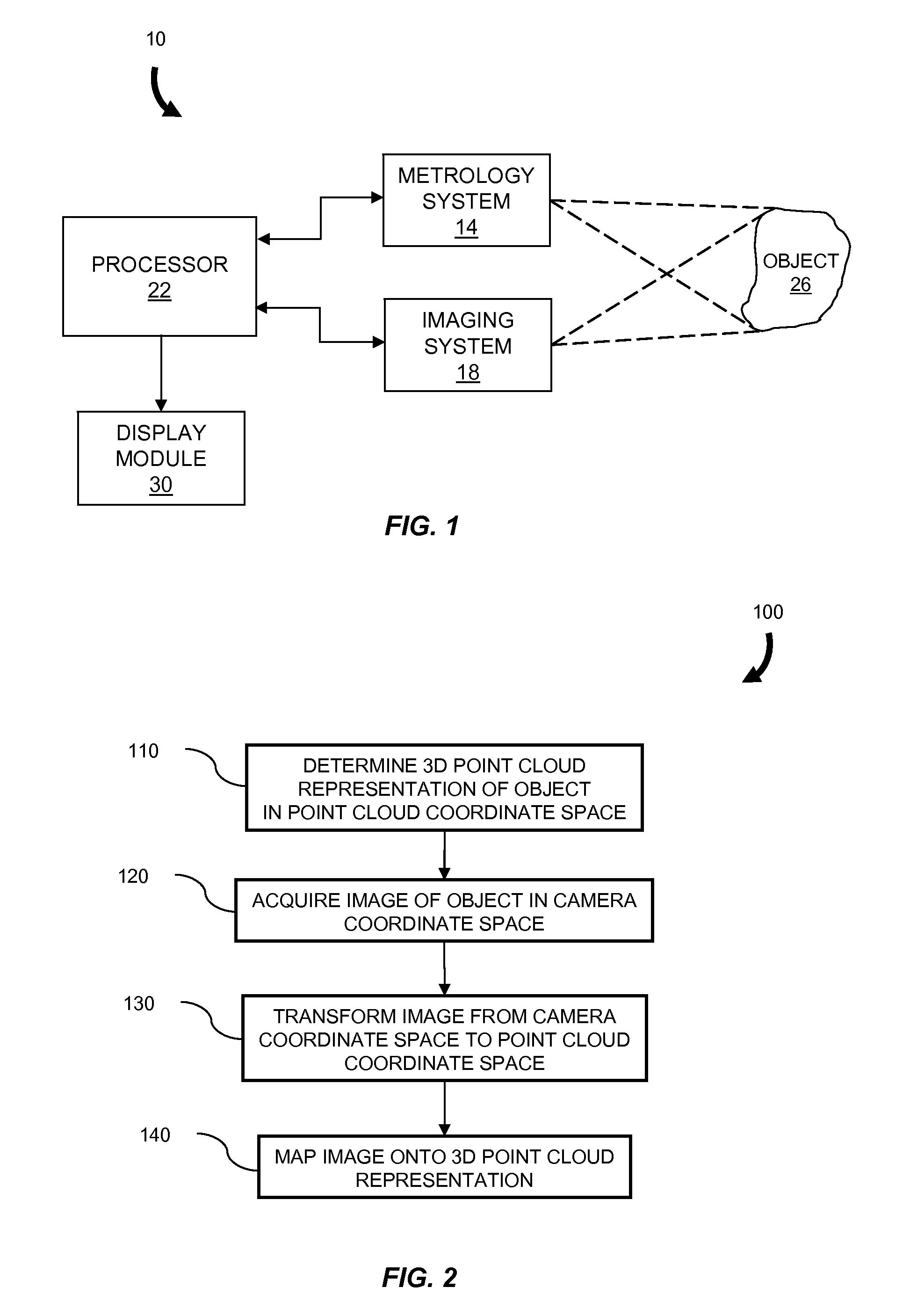
[0017]In brief overview the invention relates to a method and apparatus for generating a display of a 3D metrology surface. The method includes determining a 3D point cloud representation of a surface of an object in a point cloud coordinate space. An image of the object is acquired in camera coordinate space and mapped onto the 3D point cloud representation to generate a display of the surface of the object. If necessary, the image is transformed from the camera coordinate space to the point cloud coordinate space prior to being mapped onto the 3D point cloud representation.

[0018]The present teaching will now be described in more detail with reference to exemplary embodiments thereof as shown in the accompanying drawings. While the present teaching is described in conjunction with various embodiments and examples, it is not intended that the present teaching be limited to such embodiments. On the contrary, the present teaching encompasses various alternatives, modifications and equ...


PUM


Abstract

Described are a method and apparatus for generating a display of a three-dimensional (“3D”) metrology surface. The method includes determining a 3D point cloud representation of a surface of an object in a point cloud coordinate space. An image of the object is acquired in a camera coordinate space and then transformed from the camera coordinate space to the point cloud coordinate space. The transformed image is mapped onto the 3D point cloud representation to generate a realistic display of the surface of the object. In one embodiment, a metrology camera used to acquire images for determination of the 3D point cloud is also used to acquire the image of the object so that the transformation between coordinate spaces is not performed. The display includes a grayscale or color shading for the pixels or surface elements in the representation.

Description

RELATED APPLICATIONS[0001]This application claims the benefit of the earlier filing dates of U.S. Provisional Patent Application Ser. No. 61 / 155,200, filed Feb. 25, 2009, titled “Lofting a Two-Dimensional Image onto a Three-Dimensional Metrology Surface,” U.S. Provisional Patent Application Ser. No. 61 / 155,260, filed Feb. 25, 2009, titled “Integrating True Color Imaging into a Three-Dimensional Metrology System,” and U.S. Provisional Patent Application Ser. No. 61 / 179,800, filed May 20, 2009, titled “Shape and Shade True Color Display in a Dynamic Three-Dimensional Metrology System,” the entireties of which are incorporated herein by reference.FIELD OF THE INVENTION[0002]The invention relates generally to the field of non-contact three-dimensional metrology and more specifically to the generation of grayscale and color displays for three-dimensional surface measurement data.BACKGROUND OF THE INVENTION[0003]Precision non-contact three-dimensional (“3D”) metrology techniques based on ...

Claims


Application Information

Patent Timeline
Patent Type & Authority Applications(United States)
IPC IPC(8): H04N13/02G06T15/00
CPCG01B11/2513G01B11/2509
Inventor DILLON, ROBERT F.FILLION, TIMOTHY I.KROHG, OLAF N.JUDELL, NEIL H. K.
Owner DENTAL IMAGING TECH
Why Eureka
Try Eureka